
User`s guide

List of Figures
12 Adept Quattro s650H Robot User’s Guide, Rev A
Figure 7-3. Tool Flange Dimensions, 60° Platform . . . . . . . . . . . . . . . . . . . . . . . . . . . . . . . 85
Figure 7-4. Tool Flange Dimensions, 185° Platform . . . . . . . . . . . . . . . . . . . . . . . . . . . . . . 85
Figure 7-5. Arm Travel Volume . . . . . . . . . . . . . . . . . . . . . . . . . . . . . . . . . . . . . . . . . . . . . . . 86
Figure 7-6. Robot Internal Connections Diagram . . . . . . . . . . . . . . . . . . . . . . . . . . . . . . . 87
Figure 7-7. Mounting Frame, Orthogonal View . . . . . . . . . . . . . . . . . . . . . . . . . . . . . . . . . 91
Figure 7-8. Mounting Frame, Side View 1 . . . . . . . . . . . . . . . . . . . . . . . . . . . . . . . . . . . . . . 92
Figure 7-9. Mounting Frame, Side View 2 . . . . . . . . . . . . . . . . . . . . . . . . . . . . . . . . . . . . . . 92
Figure 7-10. Mounting Frame, Detail 1 . . . . . . . . . . . . . . . . . . . . . . . . . . . . . . . . . . . . . . . . . 93
Figure 7-11. Mounting Frame, Detail 2 . . . . . . . . . . . . . . . . . . . . . . . . . . . . . . . . . . . . . . . . . 93
Figure 7-12. Mounting Frame, Top View . . . . . . . . . . . . . . . . . . . . . . . . . . . . . . . . . . . . . . . . 94
Figure 8-1. Securing Screw on AIB Chassis . . . . . . . . . . . . . . . . . . . . . . . . . . . . . . . . . . . . 100
Figure 8-2. Opening the AIB Chassis . . . . . . . . . . . . . . . . . . . . . . . . . . . . . . . . . . . . . . . . . 100
Figure 8-3. Connectors on AIB Chassis . . . . . . . . . . . . . . . . . . . . . . . . . . . . . . . . . . . . . . . 101
Figure 8-4. Ground Screw on AIB Chassis . . . . . . . . . . . . . . . . . . . . . . . . . . . . . . . . . . . . . 101
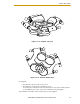
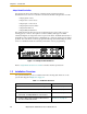
Figure 8-5. Status Display Panel, Showing 4 hex-head Screws . . . . . . . . . . . . . . . . . . . . 104
Figure 8-6. Battery Bracket on Status Display Panel . . . . . . . . . . . . . . . . . . . . . . . . . . . . 104
Figure 8-7. SPEC Utility Load Function . . . . . . . . . . . . . . . . . . . . . . . . . . . . . . . . . . . . . . . . 107
Figure 8-8. SPEC Save Specification Menu . . . . . . . . . . . . . . . . . . . . . . . . . . . . . . . . . . . 108
Figure 9-1. AIB and Base, Showing Non-anodized Aluminum . . . . . . . . . . . . . . . . . . . . 110
Figure 9-2. Joint, Between AIB and Base, to be Caulked . . . . . . . . . . . . . . . . . . . . . . . . 111
Figure 9-3. AIB Cable Seal Housing (left), Installed (right) . . . . . . . . . . . . . . . . . . . . . . . 114
Figure 9-4. Cable Entry Top Cover Assembly . . . . . . . . . . . . . . . . . . . . . . . . . . . . . . . . . . 115
Figure 9-5. Bottom of Cable Entry Top Cover, CF Frame . . . . . . . . . . . . . . . . . . . . . . . . 115
Figure 9-6. Adapting a Module to the Cable Size, Checking the Gap . . . . . . . . . . . . 115
Figure 9-7. Greasing a Roxtec Module . . . . . . . . . . . . . . . . . . . . . . . . . . . . . . . . . . . . . . . 116
Figure 9-8. Installing Roxtec Modules into the Frame . . . . . . . . . . . . . . . . . . . . . . . . . . . 116
Figure 9-9. Tightening the Compression Unit . . . . . . . . . . . . . . . . . . . . . . . . . . . . . . . . . . 116
Figure 9-10. Cable Entry Assembly with Cables . . . . . . . . . . . . . . . . . . . . . . . . . . . . . . . . . 117
Figure 9-11. Ground Lug Attachment on the AIB . . . . . . . . . . . . . . . . . . . . . . . . . . . . . . . 117
Figure 9-12. Installing Cable Entry Top Cover Assembly . . . . . . . . . . . . . . . . . . . . . . . . . . 118