
User`s guide


Chapter 7: Adept DeviceNet
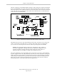
When using the open-style terminating resistor, connect a 121 ohm, ¼ W resistor to CAN_H
and CAN_L (between blue and white data-pair wires).
Figure 7-6. Example of a Terminating Resistor Installation on a DeviceNet Bus
Power Supply and the DeviceNet Bus
The DeviceNet network allows distribution of power supplies on the network cable system. Fol-
low these general rules to achieve safe and reliable operation:
l
Use power supplies rated at 24 V.
l
Minimize installation problems by using a single power supply with sufficient current
to operate all the attached nodes. This must comply with national and international
safety standards.
l
Make sure that each power supply incorporates current-limit protection.
l
Make sure each power supply is temperature-compensated.
l
Provide over-current protection for each segment of your DeviceNet cable installation.
The SmartController EX CAN driver (CAN_H/CAN_L) is protected for shorts to the power ter-
minals. The driver is protected for voltages in the range from -27 to +40 V.
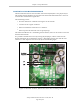
By default, the 24 V supply for the DeviceNet bus on the SmartController is disabled.
If you do want the controller to supply 24 V, two jumpers need to be moved on JP1, on the
SmartController board. To do this, move the jumpers from the EXT position to the INT pos-
ition. See Figure 7-5.
l
The jumpers provide an internal source of 24 V and GND from the EX controller for the
CAN+/CAN- lines.
l
Power is polyfuse-protected and can source 24 V (equal to controller V
IN
) at up to 1.0 A.
l
Power is diode-protected so it cannot back-drive the controller power.
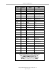
Power Capabilities of a DeviceNet Cable System
A DeviceNet cable system has several power rating constraints. The cable type and the length
of the cable affect the maximum current on a cable. Thick and thin cable have:
l
24 VDC power rating
l
Optional power-supply tabs
Adept SmartController EX User’s Guide, Rev. D
Page 90 of 94