
User`s guide


Chapter 6: sDIO Module
Labeling Cables
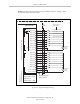
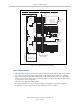
The X3 and X4 input connectors on the front of the sDIO module are similar except that X3
handles the group 1 and group 2 input signals and X4 handles the group 3 and group 4 input
signals. The optional digital input cables can be connected to either X3 or X4. Make sure to
clearly label the cables once you have completed your installation so that the cables do not get
swapped by mistake. See the warning that follows.
The X1 and X2 output connectors are also similar except that X1 handles the group 1 and
group 2 output signals and X2 handles the group 3 and group 4 output signals. The optional
digital output cables can be connected to either X1 or X2. Make sure to clearly label the cables
once you have completed your installation so that the cables do not get swapped by mistake.
See the warning that follows.
WARNING:Clearly label the X1 to X4 digital I/O cables so that they are
always plugged into the correct connectors. Swapping the X3 and X4 or
X1 and X2 cables could cause damage to your equipment. Depending on
the installation, this could potentially cause injury to personnel in the area.
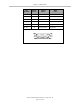
Input and Output Cable Wiring Information
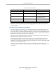
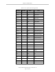
The pinouts, signal names, and wire color information for the input and output cables are
shown in the next four tables.
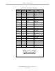
Table 6-5. X3 Input Cable Pin Assignments
Pin
Number
Signal
Group
Signal
Name
Wire
Color
X3–15 1 1033 red/white
X3–6 1 1034 orange
X3–16 1 1035 green/white
X3–7 1 1036 blue
X3–17 1 1037 blue/white
X3–8 1 1038 white/black
X3–18 1 1039 black/red
X3–9 1 1040 red/black
X3–25 1 group 1 return blue/red
X3–26 1 group 1 return red/green
X3–10 2 1041 green/black
X3–1 2 1042 black
X3–11 2 1043 orange/black
X3–2 2 1044 white
Adept SmartController EX User’s Guide, Rev. D
Page 76 of 94