
User`s guide


Chapter 6: sDIO Module
In the following situations, you must go through a configuration process to modify the sDIO
modules:
l
when you have more than two sDIO modules
l
when you choose not to use the default I/O configuration (blocks 16 and 17)
l
when you replace an sDIO module in either of the two preceding situations
NOTE:The first two sDIO modules can use the default signal configuration, with
blocks 16 and 17; each additional sDIO module must be assigned unique block
numbers.
In these cases you will use Adept ACE Configuration Tools to select the block number and to
assign the Input and Output signals. Refer to the Adept ACE User'sGuide, Digital I/O Con-
figuration, for details on configuring nodes and gadgets.
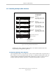
From the Adept ACE software:
1.
Double-click on the controller in the tree structure pane.
This will open the object editor for the controller.
2.
Click the Configure tab, check Configure Controller, and click Next.
3.
Click the Configuration tab.
l
Select DIGITAL_INPUT to modify the input settings.
l
Select DIGITAL_OUTPUT to modify the output settings.
4.
Modify or add signal ranges, as needed.
l
If a signal range is not present, click Add to add it.
l
Modify existing values with Edit.
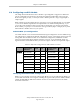
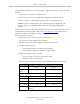
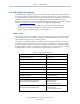
The following table describes the items on the Add/Edit Statement editor window.
Field Description
Input Output
Statement
Type
input_signal output_signal
Item Values
signalid 1001 - 1999 1 - 999
id
1
0 - 31 0 - 31
bit 0 - 31 0 - 31
length 1-32 1 - 32
signaltype adept for sDIO module; devicenet for DeviceNet con-
nection
Adept SmartController EX User’s Guide, Rev. D
Page 65 of 94