
User`s guide


Chapter 6: sDIO Module
WARNING:Remove power from the controller before plugging in or
unplugging any IEEE-1394 cables to SmartServo IEEE-1394 connectors.
Failure to remove power could result in unpredictable behavior by the
system.
5.
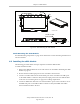
Connect a user-supplied ground wire to earth ground on each sDIO module.
6.
Connect the 24 VDC input power to the controller.
6.3 sDIO Module Connectors and Indicators
SF
IEEE-1394
X2
SC-DIO
LINK
*S/N 3563-XXXXX*
X1
24V 0.5A
R
OK
X4
- + - +
1.1 1.2
XDC1 XDC2
X3
1
2
3
7
4
5 6
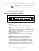
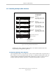
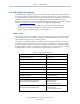
Figure 6-5. sDIO Connectors and Indicators
1.
Status LEDs.
Two LEDs indicate link status of the IEEE 1394 connection and system status.
LINK: Green LED = communication with another device over IEEE 1394 connection
OK.
OK/SF: Red LED = output driver fault detected due to excessive temperature or current
(output is automatically shut down), solid green LED = communication with controller
OK, blinking green = not configured in software.
2.
IEEE 1394 ports: Connects to one of the SmartServo ports on controller or IEEE 1394
ports on additional sDIO modules.
3.
X1 Output: 44-pin female D-sub connector, for digital output signals 0033-0048.
4.
X2 Output: 44-pin female D-sub connector, for digital output signals 0049-0064.
5.
X3 Input: 26-pin female D-sub connector, for digital input signals 1033-1048.
6.
X4 Input: 26-pin female D-sub connector, for digital input signals 1049-1064.
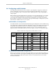
NOTE:For installations that use two or more sDIO modules, the above signal num-
bers apply to the signals for the first sDIO module. See Modifying the Default sDIO
Configuration on page 64 for information on configuring more sDIO modules.
7.
Two 24 VDC connectors: Connect power from the unused XDC connector on the
SmartController to the XDC1 connector on the sDIO module (see Connecting Power on
page 21 for power specifications).
Adept SmartController EX User’s Guide, Rev. D
Page 63 of 94