
User`s guide


Chapter 3: Operation
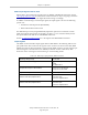
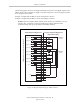
The following figure shows two examples of different connections to the digital outputs on the
XDIO connector. The examples are negative common and positive common using the internal
24 V and ground connections.
Example 1: outputs 0001 to 0004 are shown with positive common.
Example 2: outputs 0005 to 0008 are shown with negative common.
NOTE:These are examples. Either method can be used, in any combination, on any
channel. Also, an external customer-provided power supply could have been
provided instead of the power provided on the XDIO connector.
Example 1
Example 2
Signal 0001
(equivalent circuit)
Signal 0002
Signal 0003
Signal 0004
Signal 0005
Signal 0006
Signal 0007
Signal 0008
Adept-Supplied Equipment Customer-Supplied Equipment
(Typical Examples)
Load
Load
Load
Load
XDIO Connector on the Controller - Outputs
25
26
27
28
29
30
31
32
33
34
35
36
37
38
39
40
41
42
43
44
45
46
47
48
49
50
+
–
+
–
+
–
+
–
+
–
+
–
+
–
+
–
Sourcing
Sinking
+24 V (1 A)
X
X
Ground
Figure 3-6. Digital Output Wiring for XDIO Connector
Adept SmartController EX User’s Guide, Rev. D
Page 47 of 94