
User`s guide


Chapter 3: Operation
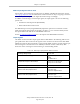
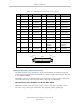
Table 3-10. DIO Input Circuit Specifications (XDIO connector)
Operational voltage range 0 to 30 VDC
OFF state voltage range 0 to 3 VDC
ON state voltage range 10 to 30 VDC
Typical threshold voltage V
in
= 8 VDC
Operational current range 0 to 7.5 mA
OFF state current range 0 to 0.5 mA
ON state current range 2.5 to 7.5 mA
Typical threshold current 2.0 mA
Impedance (V
in
/I
in
) 3.9 K Ω minimum
Current at V
in
= +24 VDC I
in
≤ 6 mA
Turn-on response time (hardware)
Software scan rate/response time
5 µsec maximum
1 ms scan cycle/
1 ms max response time
Turn-off response time (hardware)
Software scan rate/response time
5 µsec maximum
1 ms scan cycle/
1 ms max response time
NOTE:The input current specifications are provided for reference; voltage sources
are typically used to drive the inputs.
NOTE: When the program task priorities are properly set, there is a 1ms maximum
latency for the fast inputs when used with the eV+ INT.EVENT instruction.
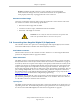
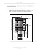
In the following figure, example 1 shows inputs (1001 to 1004) with a negative common,
example 2 shows inputs (1005 to 1008) with a positive common, and example 3 shows inputs
(1009 to 1012) with an independent power supply (no common).
NOTE: These are examples. Either method can be used on any channel.
Adept SmartController EX User’s Guide, Rev. D
Page 44 of 94