
User`s guide


Chapter 3: Operation
NOTE:These contacts do not indicate the status of any connections below the User
E-Stop contacts. Thus, they will NOT indicate the status of the Line E-Stop, MCP
ENABLE, or the Muted Safety gate. If you have a specific need in this area, contact
Adept Customer Service for information on alternate indicating modes.
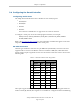
Two pairs of pins on the XUSR connector (pins 7, 20 and 8, 21) provide voltage-free contacts,
one for each channel, to indicate whether the E-Stop chain, as described above, on that channel
is closed. Both switches are closed on each of the redundant circuits in normal operation (no
E-Stop). The user may use these contacts to generate an E-Stop for other equipment in the work-
cell. The load on the contacts must not exceed 40 VDC or 30VAC at a maximum of 1 A.
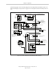
These voltage-free contacts are provided by a redundant, cyclically-checked, positive-drive,
safety relay circuit for Category 3 PL-d per ENISO 13849 operation (see the figure CAT-3 E-
Stop Circuit on XUSR and XFP Connectors on page 38 and the table Contacts Provided by the
XFP Connector on page 36 for the customer E-Stop circuitry).
Line E-Stop Input
The XUSR connector on the controller contains a two-channel Line E-Stop input for workcell or
other equipment emergency-stop inputs. Generally, the customer E-Stop Indication contact out-
puts are used to generate an emergency stop in such external equipment. Thus, if one were to
wire the same equipment’s outputs into the customer E-Stop input (that is, in series with the
local robot’s E-Stop push-buttons), a lock-up situation could occur.
The Line E-Stop input comes into the circuit at a point where it cannot affect the customer E-
Stop indication relays and will not cause such a lock-up situation. For any situation where two
systems should be cross-coupled, for example, the customer E-Stop indication of one controller
is to be connected to the input of another controller, the Line E-Stop input is the point to bring
in the other controller’s output contacts. See the figure CAT-3 E-Stop Circuit on XUSR and XFP
Connectors on page 38 for more information.
Do not use the Line E-Stop for such devices as local E-Stop push-buttons, since their status
should be reported to the outside on the local user E-Stop indication output contact while the
Line E-Stop inputs will not.
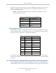
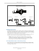
Muted Safety Gate E-Stop Circuitry
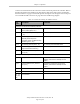
Two pairs of pins on the XUSR connector (pins 5, 18 and 6, 19) provide connections for a
safety gate designed to yield an E-Stop allowing access to the workspace of the robot in
Manual mode only, not in Automatic mode. It is up to the customer to determine if teaching
the robot in Manual Mode, by a skilled programmer (See Qualification of Personnel in the
Adept Robot Safety Guide), wearing safety equipment and carrying an Adept pendant, is allow-
able under local regulations. The E-Stop is said to be “muted” in Manual mode (for the cus-
tomer E-Stop circuitry, see the figures and tables at the beginning of the section Connecting
User-Supplied Safety and Power-Control Equipment on page 34).
The muted capability is useful for a situation where a shutdown must occur if the cell gate is
opened in Automatic mode, but you need to open the gate in Manual mode. If the mute gate is
opened in Automatic mode, the robot defaults to Manual mode operation when power is re-
enabled. In muted mode, the gate can be left open for personnel to work in the robot cell.
However, safety is maintained because of the speed restriction.
Adept SmartController EX User’s Guide, Rev. D
Page 40 of 94