
User`s guide


Chapter 3: Operation
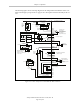
connector are both female D-sub connectors located on the front panel of the controller. Refer to
the following table for the XUSR pin-out descriptions. Refer to the table Contacts Provided by
the XFP Connector on page 36 for the XFP pin-out descriptions. See the figure CAT-3 E-Stop Cir-
cuit on XUSR and XFP Connectors on page 38 for the XUSR wiring diagram.
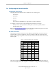
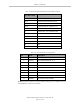
Table 3-6. Contacts Provided by the XUSR Connector
Pin
Pairs
Description Comments
Voltage-Free Contacts Provided by Customer
1, 14 User E-Stop CH 1 (mushroom push-
button, safety gates, etc.)
N/C contacts, Shorted if NOT Used
2, 15 User E-Stop CH 2 (same as pins
1, 14)
N/C contacts, Shorted if NOT Used
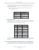
3, 16 Line E-Stop (used for other robot or
assembly line E-Stop inter-
connection. Does not affect E-Stop
indication (pins 7, 20))
N/C contacts, Shorted if NOT Used
4, 17 Line E-Stop (same as pins 3, 16) N/C contacts, Shorted if NOT Used
5, 18 Muted safety gate CH 1 (causes E-
Stop in Automatic mode only)
N/C contacts, Shorted if NOT Used
6, 19 Muted Safety Gate CH 2 (same as
pins 5, 18)
N/C contacts, Shorted if NOT Used
Voltage-Free Contacts provided by Adept
7, 20 E-Stop indication CH 1 Contacts are closed when Front Panel,
pendant, and customer E-Stops are not
tripped
8, 21 E-Stop indication CH 2 (same as
pins 7, 20)
Contacts are closed when Front Panel,
pendant, and customer E-Stops are not
tripped
9, 22 Manual/Automatic indication CH 1 Contacts are closed in Automatic mode
10, 23 Manual/Automatic indication CH 2 Contacts are closed in Automatic mode
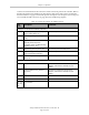
11, 12,
13, 24,
25
No connection
Adept SmartController EX User’s Guide, Rev. D
Page 35 of 94