
User`s guide


Chapter 3: Operation
and other communication parameters, use the eV+ FSET program instruction. The eV+ des-
ignations for these ports, when referenced in the eV+ ATTACH or FSET instructions, are
shown in the following table.
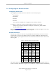
NOTE:To configure the port speed and other communications parameters, use the
eV+ FSET program instruction.
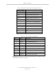
Table 3-4. Serial Connectors and eV+ Designations
Connector eV+ Designation
RS-232/Term SERIAL:0
RS-232-1 SERIAL:1
RS-232-2 SERIAL:2
RS-422/485 SERIAL:3
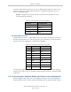
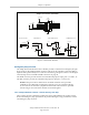
RS-422/485 Connector
The RS-422/485 connector is a 9-pin DB9 male connector. The pin assignments are shown in
the following table. RS-422 is a point-to-point protocol for connecting to a single destination.
This port can also be configured as a multidrop port (RS-485).
Table 3-5. RS-422/485 Connector Pin Assignments
Pin Signal Type
1 N/C
2 RXD+ Input
3 TXD+ Output
4 TXD- Output
5 GND Ground
6 RXD– Input
7 N/C
8 EXPIO_5V Output
9 GND Ground
To change the configuration of the RS-422/485 port, see Configuring Serial Ports on page 33.
See the previous table for the eV+ designation when referenced in the eV+ ATTACH or FSET
instructions.
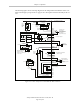
3.5 Connecting User-Supplied Safety and Power-Control Equipment
The user-supplied safety and power-control equipment connects to the system through the
XUSR and XFP connectors on the controller. The XUSR connector (25-pin) and XFP (15-pin)
Adept SmartController EX User’s Guide, Rev. D
Page 34 of 94