
User`s guide


Chapter 3: Operation
3.4 Configuring the SmartController
Configuring Serial Ports
The Adept SmartController EX motion controller has four serial I/O ports:
l
RS-232/Term
l
RS-422/485
l
RS-232-1
l
RS-232-2
See Connectors and Indicators on page 27 for the connector locations.
To configure a serial port, use the eV+ FSET program instruction, for example:
FSET (lun.num) "/BYTE_LENGTH 8 /STOP_BITS 1 /FLOW XON_XOFF /PARITY
NONE /SPEED 57600"
Refer to the eV+ Language User's Guide for more information on FSET. This applies to all of the
Adept SmartController EX motion controller's serial ports.
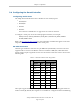
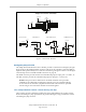
RS-232 Connectors
All three types of RS-232 connectors are 9-pin DB9 male (standard PC) connectors. The user-
supplied cable to connect to the RS-232 connectors should be a DB9, F/F, null-modem data-
transfer cable. The pin assignments are the same for all three connectors and are shown in the
following table.
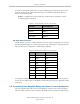
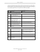
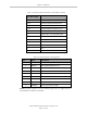
Table 3-3. RS-232 Connector Pin Assignments
Pin RS-232-1 & -2 RS-232/Term
Signal Type Signal Type
1 Reserved - N/C -
2 RXD Input RXD Input
3 TXD Output TXD Output
4 Reserved - N/C -
5 GND Ground GND Ground
6 Reserved - N/C -
7 RTS Output RTS Output
8 CTS Input CTS Input
9 Reserved - N/C -
These ports support the RTS and CTS signals used for hardware handshaking (also known as
modem control). By default, these signals are not enabled. To configure hardware handshaking
Adept SmartController EX User’s Guide, Rev. D
Page 33 of 94