
User`s guide


Chapter 3: Operation
3.2 Front Panel
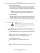
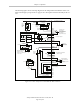
The following figure shows an Adept Front Panel.
2
3
4
5
1
STOP
R
Figure 3-2. Front Panel
Before running programs, either the optional Adept Front Panel or user-supplied switches for
High Power On/Off, MAN/AUTO, and E-Stop must be connected to the XFP connector on the
Adept SmartController EX motion controller.
NOTE:Safety regulations dictate the sequence of events required for the user to
enable high power. For instance, a user may be required to press the High Power
On button on the Front Panel after pressing the COMP/PWR button on the pendant
or issuing the eV+Enable Power command. Users cannot jumper this button input
and still enable power (see your robot manual for further details).
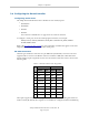
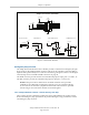
1.
XFP connector
Connects to the XFP connector on the controller.
2.
System 5 V Power-On LED
Indicates whether or not power is connected to the controller.
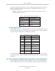
3.
Manual/Automatic Mode Switch
Switches between Manual and Automatic mode. In Automatic mode, executing pro-
grams control the mechanism, and the mechanism can run at full speed.
In Manual mode, the system limits mechanism speed and torque, to reduce the risk to
an operator working in the cell. It is the user's responsibility to determine if this is
allowed under local regulations. Manual mode initiates software restrictions on robot
speed, commanding no more than 250 mm/sec as required by RIA and ISO standards.
Please refer to your robot manual for further details.
Adept SmartController EX User’s Guide, Rev. D
Page 31 of 94