
User`s guide


Chapter 3: Operation
3. Bottom Three Status LEDs
NOTE:The bottom status LEDs have different meanings when the SmartCon-
troller is used with ePLC Connect software. See the the Adept ePLC Connect
User's Guide, chapter 3, for information on those LEDs with ePLC Connect.
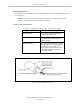
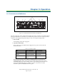
The bottom three LEDs on the front of the Adept SmartController EX motion controller
give the following information about the status of the main controller.
O = Off G = Green R = Red
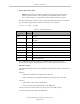
Table 3-2. LEDStatus Indicators
LED Display
1 2 3
Error
Number
Description
O-O-O 0 No error.
R-O-O 1 System clock is dead or too fast. Clock interrupts are not being
received.
O-R-O 2 Hardware configuration error.
O-O-R 4 Memory test failure. Free storage error.
O-R-R 6 Software serial I/O configuration error.
R-R-R 7 Initial display set by hardware before software has started.
G-O-O 9 Transient display set when PCI is configured.
O-O-G C Uninitialized trap.
G-O-G D Bus error detected.
If the Adept SmartController EX motion controller displays an error, cycle the
power off, then on again. If the problem persists, contact Adept Customer Service.
4.
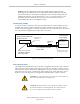
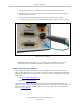
SW1 DIP switches
The definition for DIP switches on the Adept SmartController EX motion controller is as
follows:
Switch 1:
l
OFF: use IP address from configuration on SD card
l
ON: use default factory IP address (printed on the bottom of the controller)
Switch 2:
l
OFF: normal connection through Ethernet
l
ON: communication through RS-232 on the TERM port
Switch 3 and 4: reserved for future use; always leave in the OFF position.
In normal operation, all switches should be OFF.
Adept SmartController EX User’s Guide, Rev. D
Page 28 of 94