
User`s guide


Adept SmartController EX User’s Guide, Rev. D
Page 27 of 94
Chapter 3: Operation
3.1 Connectors and Indicators
1
2 4
7
9
10
11 188
3
5
6
12 13 14 15 16 17
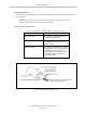
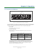
Figure 3-1. SmartController EXConnectors and Indicators
All of the connectors on the Adept SmartController EX motion controller use standard-density
spacing, D-subminiature connectors. For customization purposes, the user needs to provide
connectors of the appropriate gender and pin count, or use optional Adept cables.
1.
SD Card Slot
See Installing an SD Card on page 20.
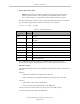
2.
Top Three Status LEDs
The top three two-color LEDs indicate diagnostic test, power control, and com-
munication status.
Table 3-1. Controller LEDs
LED Green Indicates Red Indicates
OK/SF System OK System Fault
HPE/ES High Power Enabled E-Stop Open
FW/HD SmartServo Con-
nection
Read/Write from SD
card
During system bootup, the red OK/SF and HPE/ES LEDs are lit and the red
FW/HD LED blinks. After system bootup, the OK/SF LED should show green. If
the HPE/ES LED shows red, the E-Stop circuit is open. During SD card reads and
writes, the FW/HD LED pulses red. When a robot is connected on one of the
SmartServo ports, the FW/HD LED shows green.