
User`s guide


Chapter 2: Installation
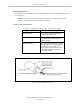
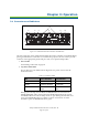
NOTE:The power switch on the Adept SmartController EX motion controller will
shut down just the controller. The two connectors, XDC1 and XDC2, are always con-
nected to each other, so a secondary device will maintain power after the controller
is shut down.
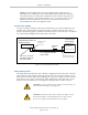
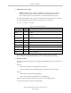
Chassis Grounding
The Adept SmartController EX motion controller is equipped with a grounding point, as
shown in the following figure. Adept recommends connecting a ground wire from the ground-
ing point on the controller to earth ground and that all other interconnected Adept components
share the same electrical ground potential. The ground wire must meet all local regulations.
Additional grounding information for other Adept products is provided in the documentation
for those products.
NOTE:The maximum length for the ground wire for the controller is 3 meters.
Grounding Point
Figure 2-8. Chassis Grounding Point
The mounting of the controller and all terminations must be performed in accordance with
local and national regulations.
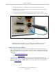
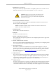
Installing 24 VDC Connectors
Use the Adept-supplied connector to connect the user-supplied 24 VDC power supply to the
Adept SmartController EX motion controller.
1.
Locate the 24 VDC connector shipped with the controller. See the following figure.
2.
Use 14 or 16 gauge wire to connect the 24 VDC power supply to the controller.
3.
Strip 7 mm of insulation from the end of the wire that connects to the positive output of
the 24 VDC supply.
4.
Insert the stripped end into the opening on the right side of the connector.
5.
Tighten the screw clamp on the connector with a small slot screwdriver (2.5 mm).
6.
Visually inspect the connection to ensure that the clamp has closed on the wire, not on
the insulation.
Adept SmartController EX User’s Guide, Rev. D
Page 23 of 94