Adept SmartController EX User's Guide Covers the SmartController EX Motion Controller and sDIO Module
Adept SmartController EX User's Guide Covers the SmartController EX Motion Controller and sDIO Module P/N:11069-000 Rev. D February, 2014 5960 Inglewood Drive • Pleasanton, CA 94588 • USA • Phone 925.245.3400 • Fax 925.960.0452 Revierstraße. 5 • 44379 Dortmund • Germany • Phone +49 (0)231 75 89 4-0 • Fax +49 231 75 89 4-50 Block 5000 Ang Mo Kio Avenue 5 • #05-12 Techplace II • Singapore 569870 • Phone +65.6755 2258 • Fax +65.
Copyright Notice The information contained herein is the property of Adept Technology, Inc., and shall not be reproduced in whole or in part without prior written approval of Adept Technology, Inc. The information herein is subject to change without notice and should not be construed as a commitment by Adept Technology, Inc. The documentation is periodically reviewed and revised. Adept Technology, Inc., assumes no responsibility for any errors or omissions in the documentation.
Table of Contents Chapter 1: Introduction 1.1 Product Description Optional sDIO Expansion Module Optional Adept T20 Pendant 9 9 9 9 1.2 Dangers, Warnings, Cautions, and Notes in Manual 11 1.3 Safety Precautions 12 1.4 What to Do in an Emergency Situation 12 1.5 Additional Safety Information 12 Manufacturer’s Declaration of Compliance (MDOC) Adept Robot Safety Guide 12 12 1.6 Manufacturer’s Declaration 13 1.
Table of Contents Remote Manual Mode User Manual/Auto Indication User High Power On Indication Remote High Power On/Off Control High Power On/Off Lamp Remote Front Panel or User-Supplied Control Panel Usage Remote Pendant Usage 41 41 41 41 42 42 43 3.6 Connecting User-Supplied Digital I/O Equipment 43 DeviceNet Connector XDIO Connector 43 43 3.7 Belt Encoder Interface Chapter 4: Maintenance 4.
Table of Contents 7.2 Limitations of the Adept DeviceNet Scanner 84 7.3 DeviceNet Port on the Controller 84 Connecting DeviceNet Hardware to the Controller Configuring DeviceNet 7.4 DeviceNet Physical Layer and Media DeviceNet Connectors Termination of the DeviceNet Network Power Supply and the DeviceNet Bus Adept SmartController EX User’s Guide, Rev.
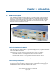
Chapter 1: Introduction 1.1 Product Description The Adept SmartController EX motion controller is a member of Adept’s family of high-performance distributed motion controllers. The Adept SmartController EX motion controller is designed for use with Adept Python Linear Modules, Adept Cobra s-Series robots, the Adept Viper line of six-axis robots, the Adept sMI6 Module for the SmartMotion product, Adept SmartServo kits, and Adept Quattro robots. Figure 1-1.
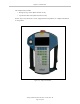
Chapter 1: Introduction The safety features include: l Emergency-stop switch (dual-channel circuit) l 3-position enable switch (dual-channel circuits) See the Adept T20 pendant User’s Guide, shipped with each pendant, for complete information on the product. Figure 1-2. Adept T20 Pendant Adept SmartController EX User’s Guide, Rev.
Chapter 1: Introduction 1.2 Dangers, Warnings, Cautions, and Notes in Manual There are five levels of special alert notation that may be used in Adept manuals. In descending order of importance, they are: DANGER: This indicates an imminently hazardous electrical situation which, if not avoided, will result in death or serious injury. DANGER: This indicates an imminently hazardous situation which, if not avoided, will result in death or serious injury.
Chapter 1: Introduction 1.3 Safety Precautions DANGER: Adept robots can cause serious injury or death, or damage to themselves and other equipment, if the following safety precautions are not observed: l l l l l All personnel who install, operate, teach, program, or maintain the system must read this guide, read the Adept Robot Safety Guide, and complete a training course for their responsibilities in regard to the system.
Chapter 1: Introduction 1.6 Manufacturer’s Declaration The Manufacturer’s Declaration of Incorporation and Conformity for Adept robot systems can be found on the Adept website, in the Download Center of the Support section. http://www.adept.com/support/downloads/file-search NOTE: The Download Center requires that you are logged in for access. If you are not logged in, you will be redirected to the Adept website Login page. 1. From the Download Types drop-down list, select Manufacturer Declarations. 2.
Chapter 1: Introduction Related Manuals This manual covers the installation and maintenance of an Adept SmartController EX motion controller system, including the sDIO expansion module. There are additional manuals that cover programming the system, reconfiguring installed components, and adding other optional components. The following manuals provide information on advanced configurations and system specifications. Table 1-1.
Chapter 2: Installation 2.1 Controller Installation This equipment must be shipped and stored in a temperature-controlled environment. See the following table. It should be shipped and stored in the Adept-supplied packaging, which is designed to prevent damage from normal shock and vibration. You should protect the package from excess shock and vibration. Table 2-1.
Chapter 2: Installation 3. Remove the optional T20 pendant from its box and place it on a flat surface near the Front Panel. Repacking for Relocation If the controller needs to be relocated, reverse the steps in the installation procedure. Reuse all original packing containers and materials and follow all safety notes used for installation. Improper packaging for shipment will void your warranty.
Chapter 2: Installation 190.0 3X M3 x 6MM BOTH SIDES 2X 40356-00004 88.1 2X 25.0 44.4 21.8 3.6 TYP. 3.8 462.0 19.1 14.2 Units are mm 482.8 Figure 2-1. Rack-Mounting the Adept SmartController EX Motion Controller Panel-Mounting the Adept SmartController EX Motion Controller To panel-mount the controller, install two brackets on each side at the rear of the unit, as shown in the following figure. Use the screws from the accessories kit. 200.5 14.0 4X 40356-00000 27.4 8.1 273.9 R3.6 TYP.
Chapter 2: Installation Table-Mounting the Adept SmartController EX Motion Controller To table-mount the controller, install two brackets on each side near the bottom of the unit, as shown in the following figure. These brackets must be ordered separately. They do not come with the controller. 4X 40356-00001 R3.6 12.1 29.5 24.1 120.9 24.9 378.6 391.8 4X M3 x 6MM BOTH SIDES 16.2 16.0 Units are mm 21.6 120.9 Figure 2-3.
Chapter 2: Installation 120.9 28.1 2X 40356-00002 BOTH SIDES 16.0 8X M3 x 6MM BOTH SIDES 30.7 328.9 155.8 76.5 Units are mm 186.5 Figure 2-4. Stack-Mounting the Adept SmartController EX Motion Controller Memory Card The Adept SmartController EX motion controller is equipped with a Secure Digital™ (SD) memory card. The SD card is removable, and can be moved to another Adept SmartController EX motion controller for testing.
Chapter 2: Installation CAUTION: Do not remove the SD card when power is connected to the controller. Removing an SD Card To remove an SD card from a Adept SmartController EX motion controller: 1. Make sure that the controller is disconnected from its power source. 2. Locate the SD compartment (see the following figure). SD Card Slot Figure 2-5. SD Memory Card Compartment NOTE: If you are replacing an existing SD, the original must be sent to Adept for replacement. 3.
Chapter 2: Installation Connecting Power The Adept SmartController EX motion controller and sDIO expansion module require filtered 24 VDC power. NOTE: Users must provide their own power supply. Make sure the power cables and power supply conform to the specifications that follow. 24 VDC Power Specifications Table 2-2.
Chapter 2: Installation NOTE: The power requirements for the user-supplied power supply will vary depending on the configuration of the Adept SmartController EX motion controller and connected devices. A minimum configuration of the controller, front panel, and pendant will require 2 A at 24 VDC. However, a 24 V, 5 A power supply is recommended to allow for additional current draw from connected devices, such as external IEEE 1394 devices and digital I/O loads.
Chapter 2: Installation NOTE: The power switch on the Adept SmartController EX motion controller will shut down just the controller. The two connectors, XDC1 and XDC2, are always connected to each other, so a secondary device will maintain power after the controller is shut down. Chassis Grounding The Adept SmartController EX motion controller is equipped with a grounding point, as shown in the following figure.
Chapter 2: Installation 7. Gently pull on the wire to confirm that it is securely attached to the connector. 8. Repeat this process to connect the wire from the negative side of the power supply to the left side of the connector. 9. Connect the braided shield to the ground screw on the front of the controller. A ring lug can be used, as shown in the following figure. The ground screw is an M3. Figure 2-9.
Chapter 2: Installation WARNING: You must use cables from vendors approved by Adept that meet all specifications of the IEEE 1394 standard. Using a non-approved or inferior quality IEEE 1394 cable can cause unpredictable system performance. 2.
Chapter 3: Operation 3.1 Connectors and Indicators 10 2 4 9 8 11 18 1 3 12 5 13 6 14 7 15 16 17 Figure 3-1. SmartController EX Connectors and Indicators All of the connectors on the Adept SmartController EX motion controller use standard-density spacing, D-subminiature connectors. For customization purposes, the user needs to provide connectors of the appropriate gender and pin count, or use optional Adept cables. 1. SD Card Slot See Installing an SD Card on page 20. 2.
Chapter 3: Operation 3. Bottom Three Status LEDs NOTE: The bottom status LEDs have different meanings when the SmartController is used with ePLC Connect software. See the the Adept ePLC Connect User's Guide, chapter 3, for information on those LEDs with ePLC Connect. The bottom three LEDs on the front of the Adept SmartController EX motion controller give the following information about the status of the main controller. O = Off G = Green R = Red Table 3-2.
Chapter 3: Operation 5. SmartServo 1.1, 1.2, and 1.3 These ports connect any Adept SmartServo-compatible product to the controller via the IEEE-1394 cable. These ports are interchangeable - any one can be used. WARNING: Remove power from the controller before plugging in or unplugging any IEEE-1394 cables from these connectors. Failure to remove power could result in unpredictable behavior by the system. 6.
Chapter 3: Operation A muted safety gate that causes an E-Stop only in Automatic mode is included. Also included are contacts to report the status of E-Stop push-buttons and the Manual/Automatic switch. NOTE: The Adept SmartController EX motion controller ships with a terminator plug attached to the XUSR connector. The terminator plug must be installed in the absence of any user-supplied safety equipment used to close the E-Stop circuit.
Chapter 3: Operation 3.2 Front Panel The following figure shows an Adept Front Panel. 2 4 1 STOP 5 R 3 Figure 3-2. Front Panel Before running programs, either the optional Adept Front Panel or user-supplied switches for High Power On/Off, MAN/AUTO, and E-Stop must be connected to the XFP connector on the Adept SmartController EX motion controller. NOTE: Safety regulations dictate the sequence of events required for the user to enable high power.
Chapter 3: Operation 4. High Power On/Off Switch & Lamp Controls high power, which is the flow of current to the robot motors. Enabling high power is a two-step process. An Enable Power request must be sent from the user terminal, an executing program, or a pendant. Once this request has been made, the button light blinks, and the operator must press the button for high power to be applied. The default timeout for the button is 10 seconds.
Chapter 3: Operation 3.4 Configuring the SmartController Configuring Serial Ports The Adept SmartController EX motion controller has four serial I/O ports: l RS-232/Term l RS-422/485 l RS-232-1 l RS-232-2 See Connectors and Indicators on page 27 for the connector locations. To configure a serial port, use the eV+ FSET program instruction, for example: FSET (lun.
Chapter 3: Operation and other communication parameters, use the eV+ FSET program instruction. The eV+ designations for these ports, when referenced in the eV+ ATTACH or FSET instructions, are shown in the following table. NOTE: To configure the port speed and other communications parameters, use the eV+ FSET program instruction. Table 3-4.
Chapter 3: Operation connector are both female D-sub connectors located on the front panel of the controller. Refer to the following table for the XUSR pin-out descriptions. Refer to the table Contacts Provided by the XFP Connector on page 36 for the XFP pin-out descriptions. See the figure CAT-3 E-Stop Circuit on XUSR and XFP Connectors on page 38 for the XUSR wiring diagram. Table 3-6.
Chapter 3: Operation Table 3-7. Contacts Provided by the XFP Connector Pin Pairs Description Requirements for UserSupplied Front Panel Voltage-Free Contacts Provided by Customer 1, 9 Front Panel E-Stop CH 1 User must supply N/C contacts 2, 10 Front Panel E-Stop CH 2 User must supply N/C contacts 3, 11 Remote Manual/Automatic switch CH 1. Manual = Open Automatic = Closed Optional - jumper closed for Auto Mode-only operation 4, 12 Remote Manual/Automatic switch CH 2.
Chapter 3: Operation Table 3-8. Remote Pendant Connections on the XMCP Connector Pin XMCP (15-Pin D-Sub) Description 1, 9 Pendant E-Stop Push-button CH 1 2, 10 Pendant E-Stop Push-button CH 2 3, 11 Pendant Enable CH 1 (Hold-to-run) 4, 12 Pendant Enable CH 2 (Hold-to-run) 13 Serial GND/Logic GND 7 Pendant TXD: “eV+ to Pendant TXD” 8 Pendant RXD: “eV+ to Pendant RXD” 14 No connection 15 No connection Shield Shield GND 6 24 V 5 No connection Table 3-9.
Chapter 3: Operation The following figure shows an E-Stop diagram for the Adept SmartController EX motion controller. See Emergency Stop Circuits on page 39 for a description of the functionality of this circuit. F Internal Connections 5V 24 V E-Stop Enable XFP-7 Front Panel System Power LED Ilimit = 1.
Chapter 3: Operation Adept Front Panel Schematic ESTOPSRC XFP 24 VS MANUALSRC1 MANUALSRC2 HPLT5V 5 VD SYSPWRLT NC 16 15PDSUBM 1 2 3 4 5 6 7 8 9 10 11 12 13 14 15 ESTOPFP1 ESTOPFP2 MANUALRLY1 MANUALRLY2 HIPWRLT HIPWRREQ 17 D "System Power LED" "MANUAL/AUTO" "HIGH POWER ON/OFF" "EMERGENCY STOP" 5 VD HPLT5 V ESTOPSRC 24 VS MANUALSRC2 SYSPWRLT MANUALSRC1 2-PIN_MINI D SWL1 SW1 D SW2 HIPWRLT MANUALRLY2 MANUALRLY1 HIPWRREQ ESTOPFP2 ESTOPFP1 Figure 3-4.
Chapter 3: Operation NOTE: These contacts do not indicate the status of any connections below the User E-Stop contacts. Thus, they will NOT indicate the status of the Line E-Stop, MCP ENABLE, or the Muted Safety gate. If you have a specific need in this area, contact Adept Customer Service for information on alternate indicating modes.
Chapter 3: Operation CAUTION: If you want the cell gate to always cause a robot shutdown, wire the gate switch contacts in series with the user E-Stop inputs. Do not wire the gate switch into the muted safety gate inputs. Remote Manual Mode The Front Panel provides for a Manual Mode circuit. See Remote High Power On/Off Control and your robot manual for further details about the customer Remote Manual Mode circuitry.
Chapter 3: Operation wiring. In this situation, a second momentary contact for high power on/off would be placed in parallel with the Adept Front Panel push-button contact. This second contact should be suppressed when in Manual mode (see the note on “Single Point of Control” below). This method allows relocating the push-button switch to a more convenient location. Implementation of this method must conform to EN standard recommendations.
Chapter 3: Operation NOTE: The XMCP and XFP connectors on the controller can be interchanged without electrical damage. However, neither the Front Panel nor the pendant will work properly unless they are plugged into the correct connector. Remote Pendant Usage Customers can build an extension cable to place the pendant in a remote location. The extension cable must conform to the following specifications: l Wire Size: must be larger than 26 AWG.
Chapter 3: Operation Table 3-10. DIO Input Circuit Specifications (XDIO connector) Operational voltage range 0 to 30 VDC OFF state voltage range 0 to 3 VDC ON state voltage range 10 to 30 VDC Typical threshold voltage Vin = 8 VDC Operational current range 0 to 7.5 mA OFF state current range 0 to 0.5 mA ON state current range 2.5 to 7.5 mA Typical threshold current 2.0 mA Impedance (Vin/Iin) 3.
Chapter 3: Operation Adept-Supplied Equipment Customer-Supplied Equipment (Typical Examples) (equivalent circuit) Signal 1001 Signal 1002 XDIO Connector on Controller - Inputs Signal 1003 Signal 1004 Signal 1005 Signal 1006 Signal 1007 Signal 1008 Signal 1009 Signal 1010 Signal 1011 Signal 1012 + 1 – 2 + 3 – 4 + 5 – 6 + 7 – 8 + 9 – 10 + 11 – 12 + 13 – 14 + 15 – 16 + 17 – 18 + 19 – 20 + 21 – 22 + 23 – 24 Example 1 + – Customer power supply Ex
Chapter 3: Operation REACT Input Signals 1001 to 1012 Inputs 1001 to 1012 (only) may be used by the eV+ REACT and REACTI instructions. See the eV+ Language Reference Guide for information on these instructions. If you are going to use these instructions, you should plan your digital I/O channel usage accordingly. In addition to functioning as normal input signals, all input signals can have the following special uses: l Fast DIO eV+ Interrupt Events (INT.
Chapter 3: Operation The following figure shows two examples of different connections to the digital outputs on the XDIO connector. The examples are negative common and positive common using the internal 24 V and ground connections. Example 1: outputs 0001 to 0004 are shown with positive common. Example 2: outputs 0005 to 0008 are shown with negative common. NOTE: These are examples. Either method can be used, in any combination, on any channel.
Chapter 3: Operation Table 3-12.
Chapter 3: Operation 1. 1658661-1 Kit (Connector body, shield, enclosure, jackscrews) 2. 1658641-2 Connector body only 3. 66682-2 Contact Pin, Male, wire size 28-24 AWG (0.08-0.2 mm2 ) (Pins also available for other wire sizes, contact TE Connectivity) Norcomp Part Numbers for 50-Pin Male D-Sub Norcomp 172 series solder cup D-Sub connectors. l 172-E50-103R001 Screw-Terminal Field-Wiring Adapter Blocks Several manufacturers make screw-terminal field-wiring blocks, usually DIN-rail mountable.
Chapter 3: Operation Table 3-13.
Chapter 3: Operation SmartController EX Belt Encoder Connector 5V Typical input circuit, same for A, B, and I for both encoders. 26LS33 Encoder Channel 1 2.2K 220 2.2K A+ Encoder A– B+ B– + – I+ I– Encoder power output: 5 V at 800 mA max. (1 A current limit) Enc. Pwr Enc. Gnd Shield Encoder Channel 2 A+ A– + Encoder – B+ B– I+ I– Figure 3-7. Belt Encoder Typical Input Circuit Adept SmartController EX User’s Guide, Rev.
Chapter 3: Operation Figure 3-8. Belt Encoder Connector Adept SmartController EX User’s Guide, Rev.
Chapter 4: Maintenance 4.1 Changing the Lamp in the Front Panel High-Power Indicator The system is equipped with circuitry to detect the potentially dangerous condition of a burned-out High Power indicator on the Front Panel. If this lamp is burned out, you cannot enable high power until the lamp has been replaced. Follow this procedure to replace the High Power indicator lamp. The Adept part number for the lamp is 27400-29006. WARNING: Lockout and tagout power before servicing.
Chapter 4: Maintenance 10. Push the front cover into the body, taking care to align all of the plug-type connectors. Verify that the wires do not get crimped as you reinstall the cover. 11. Replace the two screws on the back of the body. 12. Reinstall the Front Panel in its mounting. 13. Reconnect the cable between the Front Panel and the controller. Back side of front cover High Power On/Off Lamp Body Wires between LED and body of Front Panel.
Chapter 5: Technical Specifications This chapter shows the dimensions of the Adept SmartController EX motion controller, sDIO expansion module, Adept Front Panel, and T20 pendant. 5.1 Adept SmartController EX Motion Controller Dimensions NOTE: The dimensions for the CS and CX SmartController motion controllers were the same as these. 328.9 4.4 86.0 186.5 12.1 Units are mm 189.1 Figure 5-1. Adept SmartController EX Motion Controller Dimensions Adept SmartController EX User’s Guide, Rev.
Chapter 5: Technical Specifications 5.2 sDIO Module Dimensions 328.9 4.4 *S/N 3563-XXXXX* X1 X2 X3 LINK XDC1 XDC2 24V -+ OK SF 2.5 X4 186.5 0.5A SC-DIO IEEE-1394 1.1 1.2 R -+ 5.5 Units are mm Ground Connection Point Figure 5-2. sDIO Module Dimensions Adept SmartController EX User’s Guide, Rev. D Page 56 of 94 41.
Chapter 5: Technical Specifications 5.3 Adept Front Panel Dimensions 152.4 38.7 STOP 55.9 88.9 R 16.5 30 13.1 Units are mm 129.5 4x M4 x 18 mm 76.2 6.4 6.4 Figure 5-3. Adept Front Panel Dimensions Adept SmartController EX User’s Guide, Rev. D Page 57 of 94 139.
Chapter 5: Technical Specifications 5.4 Adept T20 Pendant Dimensions Figure 5-4. T20 Pendant Dimensions Adept SmartController EX User’s Guide, Rev.
Chapter 6: sDIO Module The sDIO expansion module provides 32 optically-isolated digital inputs, 32 optically-isolated outputs, and an IEEE 1394 interface. Figure 6-1. sDIO Module 6.
Chapter 6: sDIO Module Rack-Mounting the sDIO Module To rack-mount the sDIO module in a standard 19-inch equipment rack, you must first install the mounting brackets on each side of the unit, as shown in the following figure. NOTE: These brackets must be ordered separately. They do not come with the sDIO module. 190.0 Units are mm 2x M3 x 6 mm both sides 16.0 2x 40356-00003 R 3.6 43.9 31.8 6.1 3.6 typ. 462.0 4.2 482.8 Figure 6-2.
Chapter 6: sDIO Module Panel-Mounting the sDIO Module To panel-mount the sDIO module, install one bracket on each side of the back of the unit, as shown in the following figure. Use the screws from the accessories kit. 186.5 Units are mm 14.0 27.6 10.0 4x M3 x 6 mm 273.9 16.0 6.6 2x 40356-00000 18.0 R 3.6 346.4 359.6 Figure 6-3.
Chapter 6: sDIO Module R 3.6 4x 40356-00001 12.1 29.5 24.1 120.9 24.9 378.7 391.9 Units are mm 4x M3 x 6 mm both sides 16.3 16.0 120.8 21.7 Figure 6-4. Table-Mounting the sDIO Module Stack-Mounting the sDIO Module See Stack-Mounting Components on page 18 for information on stack-mounting the sDIO module and controller. 6.2 Installing the sDIO Module The following procedure details the steps required to install the sDIO module. To install the sDIO module: 1.
Chapter 6: sDIO Module WARNING: Remove power from the controller before plugging in or unplugging any IEEE-1394 cables to SmartServo IEEE-1394 connectors. Failure to remove power could result in unpredictable behavior by the system. 5. Connect a user-supplied ground wire to earth ground on each sDIO module. 6. Connect the 24 VDC input power to the controller. 6.3 sDIO Module Connectors and Indicators 1 *S/N 3563-XXXXX* X1 X2 X3 X4 LINK XDC1 XDC2 24V 0.
Chapter 6: sDIO Module 6.4 Configuring an sDIO Module The Adept SmartController EX motion controller is preconfigured to support two sDIO modules. Its configuration is based upon an I/O block assignment method that uses 4 bytes per block and 8 signals per byte, so each byte within a block represents a range of eight Input or Output signals. Block numbers for general digital I/O can range from 16 to 31. The default block is 16 for sDIO #1, and 17 for sDIO #2.
Chapter 6: sDIO Module In the following situations, you must go through a configuration process to modify the sDIO modules: l when you have more than two sDIO modules l when you choose not to use the default I/O configuration (blocks 16 and 17) l when you replace an sDIO module in either of the two preceding situations NOTE: The first two sDIO modules can use the default signal configuration, with blocks 16 and 17; each additional sDIO module must be assigned unique block numbers.
Chapter 6: sDIO Module Field Composed Statement Description Provides a preview of the statement, based on the current settings in the Item Values field. 1 id is either the input block or output block for Adept 1394 I/Os 5. When you have configured all of the I/O, click Done. Figure 6-6. Controller Configuration Screen, Digital Input Adept SmartController EX User’s Guide, Rev.
Chapter 6: sDIO Module ROBOT 1 Input Block 1 Byte 1 XIO (1097-1104) Output Block 1 Byte 1 ROBOT 2 Input Block 3 Byte 2 XIO (1105-1108) 4 spare Byte 2 Byte 1 Byte 2 Byte 3 Byte 4 IO Blox 1 IO Blox 2 IO Blox 3 IO Blox 4 (1113-1120) (1121-1128) (1129-1136) (1137-1144) Byte 3 Byte 4 Output Block 3 Byte 1 Byte 2 XIO Internal IO IO Blox 1 IO Blox 2 IO Blox 3 IO Blox 4 (97-104) (3001-3004) (0105-112) (0113-120) (0121-128) (0129-136) Byte 2 Byte 3 Byte 4 Input Block 2 Byte 1
Chapter 6: sDIO Module Input Block 16 Byte 1 Byte 2 Byte 3 Byte 4 sDIO #1 Group 1 Group 2 Group 3 Group 4 (1033-1040) (1041-1048) (1049-1056) (1057-1064) Byte 2 Byte 3 Output Block 16 Byte 1 Group 1 Group 2 Group 3 (0033-0040) (0041-0048) (0049-0056) Byte 4 Group 4 (0057-0064) Input Block 17 Byte 1 Byte 2 Byte 3 Byte 4 sDIO #2 Group 1 (1065-1072) Group 2 (1073-1080) Group 3 Group 4 (1081-1088) (1089-1096) Output Block 17 Byte 1 Group 1 (0065-0072) Byte 2 Byte 3 Byte 4
Chapter 6: sDIO Module 6.5 Installing Multiple sDIO Modules Recommended Configurations *S/N 3563-XXXXX* X2 X1 X3 X4 LINK -+ *S/N 3563-XXXXX* X2 X1 X3 X4 24V -+ Adept sDIO Module #4 Block 19 Input Signals 1233 to 1264 Output Signals 0233 to 0264 0.
Chapter 6: sDIO Module 6.6 sDIO Digital I/O Signals The sDIO module’s digital I/O signals are 64 optically-isolated digital I/O channels (32 output and 32 input). They are wired to connectors X1 through X4, which are located on the front of the sDIO module (see the figure sDIO Connectors and Indicators on page 63). The electrical specifications for the inputs are similar to the XDIO inputs, but have a different wiring configuration.
Chapter 6: sDIO Module NOTE: The input current specifications are provided for reference. Voltage sources are typically used to drive the inputs.
Chapter 6: sDIO Module NOTE: The off-state current range exceeds the leakage current of sDIO outputs. This guarantees that the inputs will not be turned on by the leakage current from the outputs. This is useful in situations where the outputs are looped-back to the inputs for monitoring purposes. sDIO Outputs The 32 output channels are arranged in four groups of eight. Each group is isolated from the other groups and is optically isolated from the sDIO circuitry.
Chapter 6: sDIO Module Table 6-3. sDIO Chassis LEDs Illumination Upper LED (LINK) Lower LED (OK SF) None No IEEE 1394 link Local software not running Blinking Green Not Applicable Local software active, not configured in eV+ Solid Green IEEE 1394 link good Local software active, and configured in eV+ Blinking Red Not Applicable Output fault Solid Red Not Applicable Output fault A diagnostic software indicator is not available for the XDIO outputs.
Chapter 6: sDIO Module Table 6-4. sDIO Output Circuit Specifications Parameter Value Power supply voltage range 10 VDC ≤ Vsup ≤ 30 VDC Under-voltage shutdown 5 VDC ≤ Vusd ≤ 8 VDC Power supply ground current Ig ≤ 60 mA Operational current range, per channel Iout ≤ 700 mA ON state resistance (Iout = 0.5 A) R ≤ 0.32 W @ 85° C on (R 0.4 W @ 125° C) Output leakage current Iout ≤ 25 µA Turn-on response time 175 µsec. max., 80 µsec typical (hardware only) Turn-off response time 60 µsec. max.
Chapter 6: sDIO Module Adept-Supplied Equipment Wiring Terminal Block sDIO Output Group 1 Group 1 Return Group 1 Test Signal 0033 Signal 0034 Signal 0035 Signal 0036 Signal 0037 Signal 0038 Signal 0039 Signal 0040 Group 2 Power Pins (see text) Group 2 Return Group 2 Test (equivalent circuit) Signal 0041 Signal 0042 Signal 0043 Signal 0044 Signal 0045 Signal 0046 Signal 0047 Signal 0048 X2 Connector – 44-Pin Female D-Sub 25 26 38 39 40 41 42 43 44 Connect module power return directly to power sup
Chapter 6: sDIO Module Labeling Cables The X3 and X4 input connectors on the front of the sDIO module are similar except that X3 handles the group 1 and group 2 input signals and X4 handles the group 3 and group 4 input signals. The optional digital input cables can be connected to either X3 or X4. Make sure to clearly label the cables once you have completed your installation so that the cables do not get swapped by mistake. See the warning that follows.
Chapter 6: sDIO Module Pin Number Signal Group Signal Name Wire Color X3–12 2 1045 blue/black X3–3 2 1046 red X3–13 2 1047 black/white X3–4 2 1048 green X3–19 2 group 2 return white/red X3–20 2 group 2 return orange/red X3 26-pin female input connector on sDIO module Adept SmartController EX User’s Guide, Rev.
Chapter 6: sDIO Module Table 6-6.
Chapter 6: sDIO Module Table 6-7.
Chapter 6: sDIO Module Pin Number Group Number Signal Name Wire Color X1–19 2 power orange/red X1–31 2 power orange/black/white X1–32 2 power blue/black/white X1–33 2 power black/red/green X1–34 2 power white/red green X1–35 2 power red/black/green X1–36 2 power green/black/orange X1–21 2 group 2 return blue/red X1–22 2 group 2 test red/green X1 44-pin female output connector on sDIO module Table 6-8.
Chapter 6: sDIO Module Pin Number Group Number Signal Name Wire Color X2–41 3 power white/red/orange X2–42 3 power orange/white/blue X2–43 3 power white/red/blue X2–44 3 power black/white/green X2–28 3 group 3 return white/black/red X2–29 3 group 3 test red/black/white X2–7 4 0057 white/black X2–6 4 0058 blue X2–5 4 0059 orange X2–4 4 0060 green X2–3 4 0061 red X2–2 4 0062 white X2–1 4 0063 black X2–16 4 0064 blue/white X2–17 4 power black/red
Chapter 7: Adept DeviceNet DeviceNet is a low-cost communications link that connects industrial devices to a network and eliminates expensive hard-wiring. The direct connectivity provides improved communication between devices as well as important device-level diagnostics not easily available using hard-wired I/O interfaces. 7.
Chapter 7: Adept DeviceNet 7.2 Limitations of the Adept DeviceNet Scanner The DeviceNet Scanner that Adept has incorporated into the Adept SmartController EX motion controller hardware and the eV+ operating system currently supports only a subset of full DeviceNet functionality. The following is a summary of the Adept DeviceNet implementation: l l Implemented the Master-Slave operation. This is a complete subset of Peer-to-Peer operation.
Chapter 7: Adept DeviceNet NOTE: By default, Adept does not supply 24 V on the controller to power the DeviceNet bus. A separate power supply can be used to power the components on the DeviceNet bus, or the default can be overridden with jumpers. See Power Supply and the DeviceNet Bus on page 90. NOTE: The controller incorporates a 120 Ohm line termination impedance. It is important that devices connected to the network also have a terminating resistor connected between CAN-H (white) and CAN-L (blue).
Chapter 7: Adept DeviceNet The basic topology is the trunkline-dropline topology. This topology uses separate twisted-pair buses for the distribution of signals and power. The specifications allow trunk lines and drop lines made of thick or thin cable. The baud rate, maximum distance from end-to-end of the network, and cable size are dependent on each other. See the table Features of a DeviceNet Network on page 87 for further details. Figure 7-1.
Chapter 7: Adept DeviceNet Table 7-2. Features of a DeviceNet Network Network Size A maximum of 64 nodes [0 - 63] Network Length Selectable, end-to-end network distance varies with speed Data Packets 0-8 bytes Bus Topology Linear (trunk line/drop line); power and signal on the same network cable Bus Addressing Multi-Master and Master/Slave special case; polled The baud rate of the system depends on the length of the network (end-to-end) and the type of cable.
Chapter 7: Adept DeviceNet Figure 7-3. DeviceNet Thin Cable DeviceNet Connectors DeviceNet allows different connectors, which may be grouped into open and sealed connectors. The open connectors are available with screw or with crimp connectors. The sealed connectors are available in mini-style and micro-style sizes. See the following figure and table for more details. Figure 7-4. DeviceNet Connectors Table 7-4.
Chapter 7: Adept DeviceNet Termination of the DeviceNet Network The DeviceNet network uses the Controller Area Network (CAN) bus as the physical layer. This requires that the trunk line of your DeviceNet network be terminated with a resistor at each end. This terminates the signal lines. The terminating resistor: l Prevents reflection of communication signals on the network. l Connects the two signal conductors. l Must be sealed if the end node uses a sealed tee.
Chapter 7: Adept DeviceNet When using the open-style terminating resistor, connect a 121 ohm, ¼ W resistor to CAN_H and CAN_L (between blue and white data-pair wires). Figure 7-6. Example of a Terminating Resistor Installation on a DeviceNet Bus Power Supply and the DeviceNet Bus The DeviceNet network allows distribution of power supplies on the network cable system. Follow these general rules to achieve safe and reliable operation: l l Use power supplies rated at 24 V.
Chapter 7: Adept DeviceNet If the power supplies are equipped with Schottky diodes, the optional power supply tabs must be protected from bus back-feeding of current among the power supplies on the bus. Adept also recommends the use of fuse protection for every trunk line in the cable system. The maximum current rating of a thick cable trunk line is 8 A. Verify that this complies with your national and international standards.
Chapter 7: Adept DeviceNet Figure 7-7. DeviceNet Connector Pinouts Adept SmartController EX User’s Guide, Rev.
P/N:11069-000 Rev.