
User Guide
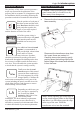


b. Fit the panel to the wall with suitable
fixings. Ensure the wall surface is flat to
prevent base distortion. There are
cable entry holes provided in the rear
of the base and around the outside
edges through the thinned out plastic
sections which may be cut away as
required.
c. The hole provided adjacent to the
mains transformer is a dedicated mains
cable entry point.
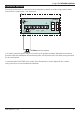
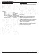
Board
There are three fuses mounted on the circuit
board, all are 20mm quick blow.
F1 1.6A - to protect the +ve line of 12V battery
F3 1A - to protect the Speaker 13V supply
F5 1A - to protect the Siren & Strobe
supply
As supplied, there are wire links are fitted across
the PA and Tamper terminals to represent a
closed circuit.
Wiring the system
Caution: Always power-down the panel
when wiring external circuits, to prevent
damage to the panel electronics.
Systematically wire and test each circuit:
ÿ
Zones, Tamper and PA circuits
ÿ
Finish by wiring any additional extension
speaker sounders, external siren (bell) /
strobe and the 13V supply.
Tamper network
The Tamper circuit is used to protect all cables
and detectors in the system from unauthorised
access including the panel cover.
The zone and PA tampers should be series wired
and connected to the TAMP terminals. The
terminalsT&Aarefortheexternal siren
tamper. Tamper alarms that occur in the Day
mode operate internal sounders only. Tamper
alarms in Set cause a full alarm condition.
Tamper is indicated by the Tamper TA
indicator.
4 4188-753 issue 1_1/03
Engineering information
J2
PA
+
TAMP
-
+13V 0V
-
STROBE
J6
+-
AC
SW1
+
TA
SCB
DB
BELL
+
-
SET
+ve
1A 1A 1.6A
BELL/STROBE
13V / SPEAKER
BATTERY
BATT
J4
F1F3F5
VR1
VOLUME
214
3
65
Factory fitted links
LD2 LD8 LD9 LD4 LD10 LD5 LD11
LD23
LD12
LD22
LD6
J1
LD3
SW2
WALK /
ALARM TEST
TAMP
ON
OFF
ENTRY TIME
PART SET
15S
30S
Mounting holes
Mounting holes
Cable entry
holes
Danger
High Voltage
~
230V 50Hz 0.2A
FUSE T125mA 250V
(ANTI-SURGE)