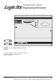
Intruder alarm system Engineering Information 1 2 3 4 5 6 TA PA ZONE Power Learn Error Day Accenta /! mini LGSIX/01 Logic Six panel with two pre learnt Keyfobs The above intruder system is designed to comply with the installation requirements of BS 4737 1986/87. 4188-753 issue 1_1/03 1 Downloaded from: http://www.guardianalarms.
Engineering information Contents Features - - - - - - - - - - - - - - - - Installation Design - - - - - - - - - - - Fixing the control panel - - - - - - - - Wiring the system - - - - - - - - - - - Tamper network - - - - - - - - - - - - Security zones - - - - - - - - - - - - - PA circuit - - - - - - - - - - - - - - - Extension speaker - - - - - - - - - - - External siren Output (Bell box) - - - - 13V Supply output - - - - - - - - - - - Set - - - - - - - - - - - - - - - - - - Factory set condition - - - - -
Logic Six intruder system Installation Design The purchase of this alarm system represents a major step forward in the protection of the property and its occupants. It is important to plan the installation before proceeding following the procedures and advice contained in this manual. Plan the position of each part of the alarm system and the cable runs. Detectors should be sited with particular regard to the degree of coverage required and the function of each of the zones.
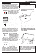
Engineering information b. c. Fit the panel to the wall with suitable fixings. Ensure the wall surface is flat to prevent base distortion. There are cable entry holes provided in the rear of the base and around the outside edges through the thinned out plastic sections which may be cut away as required. The hole provided adjacent to the mains transformer is a dedicated mains cable entry point. Mounting holes There are three fuses mounted on the circuit board, all are 20mm quick blow. F1 1.
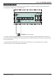
Logic Six intruder system Security zones Panel Board J2 J1 1 2 3 4 5 6 PA + TAMP +13V 0V - Terminal block is not supplied PIR Door Contact + - Alarm Door Contact Tamp All unused zones must have links fitted to disable the zone. PIR Note: The panel is supplied with wire links for unused zones. All unused zones must have links fitted to disable the zone. It is recommended that no more than 10 magnetic contacts are connected to the same zone.
Engineering information PA circuit Any quantity of normally closed type personal attack button may be wired in series and then connected to the PA circuit. Operational in Day and Set, the PA circuit will cause a full alarm condition when activated. PA is indicated on the control panel as PA. Panel Board J2 J1 1 2 3 4 5 6 PA + TAMP +13V 0V - Panic Button Panic Button PA buttons may be fitted near the front door, or in a bedroom.
Logic Six intruder system Extension speaker Extension speaker may be connected to the loudspeaker terminals to produce high volume alarm tones and low volume entry / exit fault tones. Panel J6 + - STROBE T A SCB D B BELL + - SET +ve BELL/STROBE VR1 F5 1A 13V SPEAKER Board VOLUME F3 1A 16 Ohms Extension Speaker A 16 ohms extension speaker may be wired across the speaker terminals.
Engineering information External siren Output (Bell box) The external siren (bell box) is usually installed in a high position from where the siren could be seen and heard. Terminal T A D B are for connecting to the external siren. These terminals provide a power/hold-off supply, sounder trigger and tamper circuit to protect the external siren housing.
Logic Six intruder system Panel J6 + - STROBE T A SCB D B BELL + - SET +ve BELL/STROBE Board F5 1A # Terminal block is not supplied # + STROBE T E Sonade A D B + STROBE T E A D B Sonade Where self contained / powered sounders are used, carefully follow the manufacturers instructions, match each of the terminals to those above. 13V Supply output The 13V output is to power detectors which require a voltage supply (PIR detectors etc).
Engineering information Factory set condition Keyfob 1 and 2 (supplied) Keyfobs 3 to 8 (optional) - External siren Bell Duration External siren Bell Delay - - Learnt Require learning 20 minutes No delay Zone Function The following are definitions of zone functions: Timed : This function would be used to protect the main entry/exit door of the entry route. Time inhibited (Walk through) : This is a zone which, on setting the panel, allows access to the Entry / Exit zone.
Logic Six intruder system First Power up Note: If you do not withdraw the keyfob after it is recognised by the panel then you run the risk of entering an undesired mode of operation. Before power up fit the top cover on to the base and connect the speaker wires. Leave the cover in position throughout the reset of the installation. b. Check that the factory fitted links are connected to terminals unused Zones, PA, TAMP and T-A.
Engineering information Testing the system Programs Complete the wiring of the system and then: The panel offers Full Set or selectable Part Set routine and programmable entry time. As default the panel is set for Full Set and an Entry time of 30 seconds. ÿ ÿ Program the panel. ÿ Fill in the installation log at the back of this manual and retain if for future reference. ÿ Finally explain the operation of the system to the end user.
Logic Six intruder system Walk tests Alarm tests The walk test function allows each detector to be The alarm test function allows you to test the checked in order to verify that they are Strobe, Siren (Bell), Low and High volume functioning correctly. sounders of the system, SET+ output. The Alarm Test mode could also be activated while in Walk Test mode, if you are doing this go straight to step d). To enter walk test the panel must be in Day mode with the DAY LED lit: a.
Engineering information How to learn new keyfobs Using a recognised learnt keyfob the panel can learn further keyfobs. A total of 8 keyfobs are recognised by a Panel. You may want to do this if you have acquired additional keyfobs. Using these procedures the panel will still memorise previously learnt keyfobs. New keyfobs must be learnt by the panel. Power Ensure the panel is in the day mode with the Day LED lit. You should have one learnt keyfob and the new keyfobs available.
Logic Six intruder system How to re-learn all keyfobs Using a recognised learnt keyfob the Panel can re-learn up to 8 keyfobs. You may want to do this after a keyfob is lost or stolen and you want to prevent the use of it to operate the system. Keyfobs must be learnt by each Panel installed in a system By entering the learn mode in this manner you will erase all recognition of previously learnt keyfobs at the Panel, except for the one used to enter the learn mode.
Engineering information How to learn keyfobs if none are recognised You will only need to learn keyfobs in this manner if no keyfobs are recognised by the Panel. A Panel can learn up to 8 keyfobs following power up of the intruder system. You must have all the keyfobs to be learnt available. Keyfobs can be learnt by each Panel installed in a system Ensure the Panel is connected to the intruder system and the link is fitted on the Panel PCB between Z1 and Set.
Logic Six intruder system NVM Error Alarm Cycle Counter A Non Volatile Memory NVM error indication is given by a flashing Error LED. If an NVM error occurs then you will need to re-learn all the keyfobs, see page 16. An alarm cycle is considered as the duration of an alarm from trigger to the end of 20 minutes operation of the external siren. The panel allows three alarm cycles during either set or unset period. When the third alarm cycle expires the panel is shut down, the storobe continues to operate.
Engineering information Faults removing the control panel covers. Fault conditions are often the result of minor installation errors or misinterpretation of the equipment being installed. The following points outline the most common installation and commissioning faults. Where normally open and closed detectors are being used these must be wired to a zone in the manner shown. a. The example below shows how to wire normally open detectors on zones 3. b. c. d. e.
Logic Six intruder system Specification Indicators on Control panel 6 Zones Tamper PA User keyfobs Keyfob operating range Proximity reader External siren (Bell box) Output Strobe Output Extension Speaker Exit time Entry time Full/Part Set Walk and Alarm Tests Zone Input Delay Set +ve Output Current Consumption Control panel Low voltage output Rechargeable Battery Charge Voltage Board Fuses Mains Input fuse 4188-753 issue 1_1/03 Zone 1-6 (red), Tamper TA (amber), Personal Attack-PA, Power, Learn (amber)
Engineering information Servicing organisation Details Parts Servicing organisation name: Below is a list of approved parts and accessories. _______________________________________ Telephone number: LGSIX/01 Logic Six panel (supplied with 2 learnt keyfobs) SS/F Spare Keyfob ______________________________________ Date of installation: ______________________________________ Account Number: _____________________________________ Resistance Area protection and equipment used (eg PIR, Contacts..
Intruder alarm system Operating Instructions 1 2 3 4 5 6 TA PA ZONE Power Learn Error Day Accenta /! mini Servicing organisation details Servicing organisation (Installer) name: ______________________________________________ Telephone number: _______________________________________________________________ Date of installation: _______________________________________________________________ Account number: _________________________________________________________________ 1
Operating instructions System installation Keyfobs This booklet tells you how to operate your intruder alarm system. To simplify this booklet we have assumed that the alarm system has been installed by a professional intruder alarm system installer (the installer), and that the system is operated in a “typical” way. Aspects of your system that are not “typical” will be described by your installer. To operate the alarm system you will need the keyfobs supplied with the panel.
Logic Six intruder system Personal Attack Power Indicator If you are under threat, or are being attacked, you can activate the alarm by operating the personal attack buttom in your system. The alarm system will produce a loud alarm sound, and the external siren will be turned on. The Power indicator on the control panel will light whenever the mains power supply is present. If mains power fails then the Power indicator will flash, but the system will run from its backup battery for several hours.
Operating instructions How to Set the system When you leave your premises you will need to set (or turn on) the intruder alarm system. Before setting the system you should ensure that the premises have been completely vacated and that all doors and windows are closed. Ensure that pets do not have access to the protected areas as they can cause a false alarm, unless pet immune detectors have been used, ask your installer for more information. The Day indicator should be lit at the Panel.
Logic Six intruder system How to Unset the system When you enter your premises you will need to unset (or turn off) the system. If your system had gone into alarm then be aware that intruders may be in the premises. Seek assistance before investigating the cause of the alarm and unset the system. Enter your premises by the route recommended by your installer. The system will produce an entry beep tone.
Operating instructions How to part set the system If your installer has programmed your system for part set operation you will be able to set some zones of the system while others remain unset. Part set operation is often used at night time, and it will permit you to freely walk around the bedrooms while the living area and outside doors are protected.
Logic Six intruder system Entry time:________________ Area protected Zone name Full set Part Set Zone 1 T T Zone 2 TI T Zone 3 I T Zone 4 I I Zone 5 I O Zone 6 I O O = Omited T = Timed (Entry/Exit - Zone) TI = Time Inhibited (Access zone to keypad) I = Immediate (Zone armed to give full alarm) 7
Operating instructions The Logic Six panel conforms to the requirements of the European R&TTE directive 1999/5/EC and carries the CE mark. This product is intended for use in the UK.