T E C H N O L O G I E S User Guide RAID Rack (RR2035ASDES) www.addonics.com v8.1.11 Technical Support If you need any assistance to get your unit functioning properly, please have your product information ready and contact Addonics Technical Support at: Hours: 8:30 am - 6:00 pm PST Phone: 408-453-6212 Email: http://www.addonics.
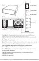
I O Front Power Switch POWER System Reset RESET Buzzer Reset Back Buzzer Punch out for USIB connectors Fans POWER LED Display FAN I O I O TEMP Punch out for USIB connectors Power Supply HDD Punch out for eSATA Punch out for port multipliers/bridges Power Switch: This is the switch to power on devices connected to the power supply. The power LED will light up to indicate power is supplied. Note: The main power switch located at the back of the enclosure must be turned on first.
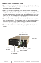
Installing drives into the RAID Rack 1. Be sure the lock on each drive door is in an unlock position. If not, use the key that comes with the Disk Array to unlock the drive door. Pull on the door lever to swing open the drive door all the way. 2. Slide a 3.5” SATA hard drive into the drive slot with the drive connector side facing in.
I O I O Top Cover Screws O 3. I 2. Locate the 2 screws at the back of the storage rack Turn screws counterclockwise to loosen. Lift the top cover and pull towards the rear end of the rack. O 1. I How to Remove the Top Cover: 3. O I 2. Align the top cover with the edges of the rack. Lay it flat on the rack and slide it towards the front of the rack. Turn screws clockwise to tighten. O 1.
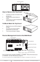
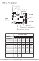
HPM-XA Port Multiplier RAID Setting Button Dip Switch SATA Host Port (Port 5) SATA Port 2 SATA Port 1 SATA Port 0 Floppy Power Connector SATA Port 3 SATA Port 4 Drive activity LED Jumper Block (J1) Error LED Jumper Block (J3) Dip Switch Settings Raid Mode 1 2 3 4 5 Individual Drive (Factory Default) OFF OFF OFF OFF OFF 0 OFF OFF ON ON ON 1 and 10 OFF OFF ON ON OFF 3 OFF OFF ON OFF OFF 5 OFF OFF OFF ON OFF Clone OFF OFF OFF ON ON Large OFF OFF ON OFF ON Ena
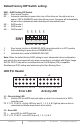
Default factory DIP Switch setting: OFF OFF OFF OFF SW1 OFF SW1 – RAID Setting DIP Switch BZS – Error buzzer function EZ – Automatic rebuilding to spare drive (one of the drives on the raid is set as a spare). If EZ is ENABLED anda drive failure occurs, the spare will automatically act as a drive replacement and rebuilding will automatically start. M2 – RAID mode 2 M1 – RAID mode 1 M0 – RAID mode 0 1 2 3 4 5 BZS EZ M2 M1 M0 1. 2. 3.
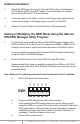
Cable Connections 1. Attach the SATA hard drives (up to 5) to the SATA ports on the Hardware Port Multiplier (HPM) using SATA cables. It is recommended to connect drives to the SATA ports 1 to 5 successively. 2. To provide power to the HPM, connect a 4-pin floppy power cable from the system power supply to the floppy power connector on the HPM. 3. Optional: Connect LEDs to the Activity & Error LED jumper block Setting or Modifying the RAID Mode Using the JMicron HW RAID Manager Utility Program: 1.
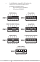
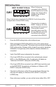
e. On the DIP switch, change (M0 to M2) setting to the desired RAID mode using the diagram below. SW1 1 ON 5 ON 4 OFF 3 Clone Mode OFF ON 2 OFF ON 1 ON SW1 RAID 0 Mode OFF OFF All settings on the diagram shows • Error buzzer function is ENABLED • EZ function is DISABLED.
RAID Setting Notes: RAID 1& RAID 10 Mode When 2 drives are SW1 1 2 3 4 5 BZS EZ M2 M1 M0 connected to the HPM-XA, and DIP switch is set to this setting, the 2 drives will be configured as a 2-drive RAID1 array. When 4 drives are connected to the HPM-XA, the 4 drives will be configured as a 4-drive RAID10 array. Clone Mode SW1 1 2 3 4 5 BZS EZ M2 M1 M0 Clone’s action is similar to RAID1. However, all of the hard drives will be mirrored.
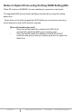
Notes on Spare Drives using the Easy RAID Setting (EZ) When EZ function is ENABLED, the auto-rebuilding to spare drive is automatic. The degraded RAID group will start rebuilding automatically by using the existing spare drive. * Spare drive can be either plugged after RAID building or a new drive can be plug as the spare drive when RAID rebuild is required. When will rebuild action start? • When the raid fails and EZ is enabled, the HPM-XA will automatically rebuild the RAID group using the spare.
RAID Rack with Port Multiplier Compatibility Note: The Port Multiplier will only work with a Port Multiplier aware host. Identify your host controller and check with its hardware manufacturer if you are unsure. Addonics offers several Port Multiplier capable host adapters. When the port multiplier (PM) is connected to a host controller with SiI3124 or SiI3132 chip, in the RAID BIOS of the host controller you will only see one drive and that is the drive connected to SATA port 1 on the Port Multiplier.
CONTACT US www.addonics.com Phone: Fax: Email: 408-573-8580 408-573-8588 http://www.addonics.