T E C H N O L O G I E S User Guide External Port Multiplier Ultra (AD5EHPMEU3) www.addonics.com v8.1.11 Technical Support If you need any assistance to get your unit functioning properly, please have your product information ready and contact Addonics Technical Support at: Hours: 8:30 am - 6:00 pm PST Phone: 408-453-6212 Email: http://www.addonics.
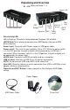
Unpacking and Overview D1 – D5: Refers to Device 1 - 5 Power LED eSATA Device Port Host LED USB 3.0 SET Power to host eSATA Button input Host Dipswitch (SW1) Power on/off Drive Activity LED: LED will light up. If the drive is being accessed, the green LED will blink. eSATA Ports:This is where you connect your eSATA devices (like your eSATA drive enclosure) Power input: Connects to 5V Power supply or USB power cable. Power on/off: This turns the port multiplier ON or OFF.
Port Multiplier Compatibility When configured as a set of individual drives and connected to a SATA or an eSATA host adapter, the Port Multiplier will only work with a Port Multiplier aware host. This includes setting up the unit with more than one array. Identify your host controller and check with its hardware manufacturer if you are unsure. Addonics offers several Port Multiplier aware host adapters. Using identical drives for all settings other than JBOD or LARGE is strongly recommended.
RAID 3 (Stripe set with dedicated parity) Number of drives: at least 3 Unit capacity: size of one member times number of members minus one. Spares: yes Fault tolerance: can withstand the loss of one drive without losing data. RAID 3 works by striping data for individual I/O blocks across all members except one, which contains parity data for the stripe set computed internally by the Port Multiplier. In the event of failure, the missing information can be calculated using the parity information.
Configuring the Port Multiplier Using Dipswitches Resetting the RAID NOTE: This procedure destroys all RAID data. It should not harm individual drives or their contents; however, creating backups of all data is strongly recommended before proceeding. Be sure the port multiplier is connected to an active host before proceeding. The port multiplier will not complete the process if it has no host connection. 1. Power down the unit and set the dip switch to the desired RAID Mode. 2.
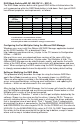
RAID Mode Switches M2, M1, M0 (SW1:3 – SW1-5) The RAID Mode switches define what type of RAID will be initialized when the unit is powered up while the RAID Mode button is held down.
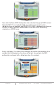
Next, click the Basic RAID Configuration tab and select the type of RAID desired. Note that RAID 1 is currently disabled as an option since more than two individual drives are available, and DELETE ALL RAID is disabled since there are currently no arrays to delete. Shown below is the same set of drives being selected as a LARGE array. Finally, click Apply.
The RAID and Disk Information screen (shown when the program was launched) will now show the Port Multiplier with an Array. The drives are now listed as M0-M4, indicating they are members of the array. If spares are present (individual drives added later, and the EZ switch is in the OFF position), they would be listed as S0, S1, etc. On the right pane, the RAID Level, status, capacity and members that are online are listed.