
Product data


APCI-7xxx-3 Figures and Tables
11 INDEX
B
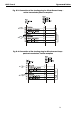
Block diagrams 21
Board configuration 26
Board test 30
C
Component scheme
APCI-7300, APCI-7420-3, APCI-500-3 18
APCI-7800-3 19
Configuration under Windows XP/2000 26
Connection cable
APCI-7500-3 40
APCI-7800-3 48
Connection examples 41
Connector pin assignment
APCI-7420-3, APCI-7300-3, APCI-7500-
3/4C 33
APCI-7500-3 32
Current loop
Cabling APCI-7300-3, APCI-74203. APCI-
7500-3/4C 46
Cabling APCI-7500-3 42
Connection of shorting plug 54
Limit values 17
Current Loop
APCI-7800-3 51
D
Dimensions 13
E
EMC
Electromagnetic compatibility 13
Energy requirements 15
F
FIFO settings under Windows 2000 27
G
Glossary 60
H
Handling of the board 12
I
Installation of the board 24
Intended use 8
Internet 31
L
Limit values 15
M
MTTTY program 55
MX module
Inserting 59
Removing 58
P
Physical set-up 13
Pin assignment
APCI-7800-3 34
R
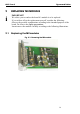
Replacing the modules 58
RS232
Cabling APCI-7300-3, APCI-7420-3, APCI-
7500-3/4C 44
Cabling APCI-7500-3 41
Cabling APCI-7800-3 49
Connection of a shorting plug 53
Limit values 16
RS422
Cabling APCI-7300-3, APCI-7420-3, APCI-
7500-3/4C 45
Cabling APCI-7500-3 41
Cabling APCI-7800-3 50
Connection of a shorting plug 53
RS422, RS485
Limit values 16
RS485
Cabling APCI-7300-3, APCI-7420-3, APCI-
7500-3/4C 45
Cabling APCI-7500-3 42
Cabling APCI-7800-3 50
S
Slot types 24
Software download 31
T
Technical data 13
Testing the board 53
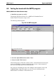
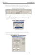
Testing the board with MTTTY 55
U
Update 31
Usage restrictions 8
User
Personal protection 11
Qualification 11
63