
Product data

APCI-7xxx-3 Figures and Tables
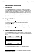
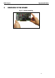
The board is to be connected to the peripheral through a shielded cable, which
shielding should be grounded on both ends.
Minimum specifications of the connection cable:
- metallised plastic hoods
- shielded cable
- cable shield folded back and firmly screwed to the connector housing.
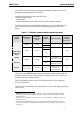
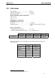
The board supports serial communication through 1, 2 or 4 asynchronous serial
ports. The use of the board depends on the following parameters (See table
below).
Table 1-1: Different communication operating modes
Plug-in
module
1
Transmission
standard
Maximum
transmission
rate
2
Optical
isolation
Interface setting
Distance
between
transmitter
and receiver
3
MX232
no
RS232 115 kbps
1 kV
-
MX232-G
30 m
MX422
no
MX422-G
RS422 115 kbps
1 kV
-
MX422-PEP
(RTS/CTS as
RS422)
1.2 km
MX485
no
automatic
transmitter control
RS485 115 kbps
automatic
transmitter control
MX485-G
1 kV
1.2 km
MXTTY
TTY (20 mA
current loop)
19.2 kbps 1 kV
standby current on
transmit and
receive channel
1 km
If the basic board APCI-7xxx-3 is used with optically isolated modules and non
isolated modules, then the safety built by the creeping distance of 3.2 mm is not
ensured for the non isolated modules.
Check the shielding capacity of the PC housing and cable prior to putting the
device into operation.
The use of the board includes observing all advises given in this manual and in the
safety leaflet.
1
MXxxx-G: MX232-G, for example, stands for a plug-in module with the RS232 standard.
The -G suffix means that the module is optically isolated. The MXTTY module is always
optically isolated.
2
Transfer rates > 115 kbps on the board xPCI-7xx0 are possible up to 1 Mbps by means of an
equipment option.
3
The indicated maximum lengths apply to normal interface cables (shielded control lead,
0.14 mm²). The length is also limited by the number of users, impedance, line capacity and
transfer rate.
9