About this manual SmartView XPro - Installation and Use First edition (April 2001) Part No. ADD0038/1 (c) 2001 Adder Technology Ltd. www.addertec.com All rights reserved. Whilst every precaution has been taken in the preparation of this manual, Adder Technology Ltd assumes no responsibility for errors or omissions. Neither is any liability assumed for damages resulting from the use of the information contained herein.
accepted for damage due to misuse or circumstances outside Adder’s control. Also Adder will not be responsible for any loss, damage or injury arising directly or indirectly from the use of this product. Adder’s total liability under the terms of this warranty shall in all circumstances be limited to the replacement value of this product. If any difficulty is experienced in the installation or use of this product that you are unable to resolve, please contact your supplier.
Contents 1. Introduction .................................................................................... 5 1.1 Key features and benefits ...................................................................... 6 1.2 SmartView XPro package contents........................................................ 7 1.3 AdderLink XR receiver package contents .............................................. 8 1.4 AdderLink Gold XR receiver package contents ..................................... 8 1.
. Using the SmartView XPro ........................................................... 39 4.1 Rear panel special function switches ..................................................... 39 4.2 Power supply connections and indicators ............................................. 39 4.3 USER display and key switch ................................................................ 39 4.4 COMPUTER display and key switch ...................................................... 40 4.5 Activity indicators ............
1. Introduction Thank you for purchasing the Adder SmartView XPro. Your SmartView XPro is a very high performance Keyboard, Video monitor and Mouse (KVM) sharing device which supports a wide range of PC hardware and software platforms. The SmartView XPro supports multiple users and enables each user to independently access the connected computers. An On-Screen-Display (OSD) menu system is provided for easy computer selection and control.
1.1 Key features and benefits Enables many computers to be independently controlled by multiple users. On-screen menu allows computers to be selected by name or description. Configurable security enables administrator to assign access rights to users. Dual-access port(s) with built-in 200 metre AdderLink extender connections enable the SmartView to be controlled from local and remote KVM consoles.
Mixed AT/PS2 keyboards and PS2/RS232 mice supported as standard. Can be cascaded to a depth of four levels to provide a video switching network. Automatically restores keyboard and mouse states when channel changed. Supports keyboard modes 1,2 and 3 and mouse prompt and stream modes for maximum compatibility. Includes screen saver, auto-scan, variable hotkey, name search options.
1.3 AdderLink XR receiver package contents (part code XXXXX) AdderLink XR receiver. Power supply suitable for your country. Installation and Use guide 1.4 AdderLink Gold XR receiver package contents (part code XXXXX) AdderLink Gold XR receiver. Power supply suitable for your country. Installation and Use guide.
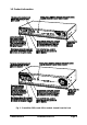
1.5 Product information Fig.
Fig.
Fig.
Fig.
2. Installation Adder explains: Flexible configuration The SmartView XPro has many ports for connection to computers, keyboards, mice, monitors and AdderLink extenders. There are no restrictions placed upon on which ports are connected to devices and you can leave any of the ports disconnected if you wish. You do not need to connect a keyboard, monitor and mouse to each user port if you do not wish to use all of these.
For the local user port connections you will need: A monitor with a standard VGA-style 15-pin analogue video connector that will work when connected directly to each of your PCs. SmartView XPro supports low and high resolution monitors. An PS/2 or AT style keyboard. If you are using an AT keyboard with a 5-pin connector you may connect this to the SmartView XPro using a standard AT to PS/2 keyboard adapter.
Use of PS/2 and RS232 style mice with the SmartView - All of the mouse connections from SmartView to PCs support either a PS/2 or an RS232 mouse. SmartView automatically converts from the PS/2 mouse commands to RS232 serial mouse commands. Serial mice types are selected by using an adapter as described in Appendix A. The SmartView will operate without a mouse connected if you do not wish to use one. 2.
Any unused computer connections can be left unconnected. To connect computers with serial mouse connections and AT style keyboard connections use the adapters specified in appendix A. If you have an existing 6-pin mini-DIN to 9-pin serial adapter that came with a mouse it may not be suitable for use with the SmartView as the are several different standard wiring configurations for these adapters.
2.4 Configuring your PCs Configure your PC in the same way that you would if your keyboard, mouse and monitor were all connected directly to your PC, but bearing in mind the following point: SmartView emulates Microsoft compatible serial, IntelliMouse and PS/2 mice, so ensure that your PC software is configured for a Microsoft mouse of the correct type. Refer to the list of supported drivers in section 2.1. 2.
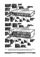
When cascading SmartView XPros keep in mind the following rules The maximum number of layers in a SmartView XPros cascade is four. You may cascade 4XPro units with 1, 2, 3 or 4 KVM links and 2XPro units with 1 or 2 KVM links. The number of KVM links that you install defines the number of simultaneous uses that are supported. Keep all cascade cables as short as possible. The video quality is maximised by using the shortest possible total cable run from computer to KVM.
The following diagrams show some typical SmartView XPro installations.
Fig.
Fig.
2.6 Maximising the video quality The SmartView XPro supports very high bandwidth video signals and resolutions up to 1900 x 1440 pixels. It regenerates the video signals using wideband amplifiers in order to minimise any loss of video quality. All video cables introduce distortion onto the video signal. For short cables this is minimal but for longer cables the loss of quality can start to become noticeable particularly at higher video resolutions.
2.7 Other useful installation information PC boot up sequence - When your PCs are powered on they communicate with any attached keyboards and mice and setup parameters required by the particular operating system. It is necessary for the SmartView to be attached and powered on during this sequence so that it can give the required responses and keep track of all the modes and settings requested by each of the connected PCs.
the SmartView's keyboard and mouse reset function (see section 4.16). This function only resets the keyboard and mouse attached to the selected user port. It does not affect the status of any of the SmartView's other ports or the CPU connections. 2.9 Hot plugging the SmartView into running systems and reenabling disconnected CPU PS/2 mouse connections It is adviseable to switch off the systems that are going to be connected to the SmartView before installation.
Type of mouse / system Connected at bootup Driver type Likely expected data format Suggested restoration PS/2 PS/2 IntelliMouse / SmartView IntelliMouse / SmartView PS/2 only IntelliMouse PS/2 only IntelliMouse PS/2 PS/2 PS/2 IntelliMouse Standard Standard Standard IntelliMouse To restore lost mouse movement on a CPU connected to the SmartView: 1) 2) 3) 4) 5) 6) Select the CPU that has lost its mouse movement Activate the on-screen menu using the keyboard hotkeys Press F1 to view additional menus S
3. Configuring the SmartView XPro 3.1 Configuration summary The SmartView is configured using the on-screen menu system which is activated by default when you first power on the system. It may also be accessed by using the keyboard 'hotkeys' (see section 4.8) or by using the SmartView's front panel keys (see section 4.6). The following steps summarise a typical configuration process.
Step 3 - Create user accounts Login to the SmartView using the ADMIN account and add user profiles and passwords for each of the system users (see section 3.4). The SmartView supports up to 16 user profiles. Step 4 - Add / edit names to identify your computers Whilst you are logged into the SmartView using the ADMIN account, create names for each of the computers that you have attached to the system. The SmartView creates default names for each of its ports (Computer 1 to Computer 16).
To switch on the password security system: From the main on-screen menu press F1 for MORE MENUS. Select SETUP OPTIONS from the menu. Move the menu bar over the SECURITY option. Press SPACE BAR to enable security. Press ESC to quit from the menu. 3.3 Setting an ADMIN password The SmartView XPro supports up to 16 user profiles. The administrator of the system can grant or deny users access to any of the connected computers and has complete control over the setup of the system.
3.4 Creating and editing user accounts To create user accounts: Ensure that you are logged on as the ADMIN user. From the main on-screen menu press F1 for MORE MENUS. Select EDIT USER LIST from the menu. Press INSERT to add a new user. Type in the name of the new user and press RETURN or ENTER. Type in the password for the new user and press RETURN or ENTER.
the port numbers will be four, six or eight digits long depending upon whether you have two, three or four levels of cascade (see figure 7). See the end of this section and section 4.10 for an explanation of how the port numbers are constructed. The SmartView XPro supports up to 512 computer names. To create computer names: Ensure that you are logged on as the ADMIN user. From the main on-screen menu press F1 for MORE MENUS. Select EDIT COMPUTER LIST from the menu. Press INSERT to add a new computer name.
Creating entries for computers connected to cascaded SmartViews You can cascade SmartView 4XPro units using one, two, three or four KVM links and SmartView 2XPro units using one or two KVM links. Section 2.5 explains the rules that you must follow when installing a SmartView cascade. The number of cascade links that you install determines the number of simultaneous users that can access computers on the cascaded SmartViews.
Fig.
Fig. 8 - Possible cascade groups and their associated names 3.6 Setting the SETUP OPTIONS and GLOBAL PREFERENCES The SETUP OPTIONS and GLOBAL PREFERENCES are system operating parameters that apply to the whole system rather than to individual users. These may only be setup or changed by the system administrator logged in using the ADMIN account. From the main menu press F1 for MORE MENUS. Use the cursor keys to position the menu bar over SETUP OPTIONS or GLOBAL PREFERENCES.
3.6.1 SECURITY Accessed from menu: SETUP OPTIONS Settings: DISABLED, ENABLED With security disabled there is no requirement for users to login to the system. All users have full access to all the connected computers and full administration rights. With security enabled, users are required to login to the SmartView. Each user is allocated access rights to computers by the system administrator and they are only able to see the computers that they have access to on their on-screen menu. 3.6.
3.6.4 KEYPAD CONTROLS Accessed from menu: SETUP OPTIONS Settings: ENABLED, DISABLED The key controls on the front of the SmartView may be disabled so that it is only possible to select the special channels "o" and "0" (the on-screen menu and the nonexistent channel zero). 3.6.5 EXCLUSIVE USE Accessed from menu: SETUP OPTIONS Settings: ALLOWED, DISABLED In normal operation, the SmartView will allow two or more users to share access to a computer.
3.6.6 MOUSE SWITCHING Accessed from menu: GLOBAL PREFERENCES Settings: ENABLED, DISABLED Like most Adder Technology KVM switches, the SmartView XPro's channel may be switched using a three button mouse or IntelliMouse (see section 4.9). Pressing the central button or wheel button together with the left hand mouse button will cause the SmartView to switch to the next available computer.
WARNING - Many modern monitors are fitted with automatic power save relays and will switch off after a few seconds if connected to an inactive PC. If you are using such a monitor you must not set the SmartView to scan ALL ports. Constant switching on and off of your monitor's relay will eventually damage your monitor. 3.6.
also controls the timeout between the local and remote access points on user ports 1 and 3. 3.6.12 RS232 Mouse Type Accessed from menu: GLOBAL PREFERENCES Settings: INTELLIMOUSE, 2 BUTTON, 3 BUTTON These setting control the type of RS232 mouse that the SmartView reports to computers. All the necessary conversions are dealt with automatically with the SmartView.
4. Using the SmartView XPro This section explains the general operation of the SmartView XPro. We recommend that you read this section before starting to use the product. 4.1 Rear panel special function switches Before powering on the SmartView ensure that the two option switches on the rear are set to the OFF (up) position. Option switch 1 is reserved for future use and option switch 2 is used to enable firmware upgrades (see section 5). 4.
4.4 COMPUTER display and key switch The COMPUTER key selects the computer port that is to be connected to the user port that is currently displayed on the green USER display (see figure 1). Pressing the key will cause the red COMPUTER display to change to the next available computer port in numerical sequence. The next available computer port is defined by the way that the SmartView XPro is configured. There are two special computer ports that may be selected using the COMPUTER key switch.
4.5 Activity indicators The SmartView XPro has a front panel activity indicator for each user port (see figure 1). The indicator will flash when keyboard or mouse data is received by the SmartView. These indicators provide a useful confirmation that the keyboards and mice connected to the SmartView are functioning normally. 4.
security system has not been enabled then this will be the next highest channel number in the sequence shown below. If password security has been enabled then you will only be able to select the computer ports that you have access to. If the front panel controls have been disabled by the administrator then you will only be able to select the special channels 'o' and '0' (the on-screen menu / login screen or nonexistent channel zero).
4.7 Logging on to the SmartView XPro If password security has been set on the system then the following login menu will appear when the SmartView is switched on or when no user is currently logged in. The previous user may have activated the screen save function (screen blanking). If so, you may need to press a key before the login menu appears. Type in you user name and password to access the SmartView. 4.
‘HOTKEYs’ and ‘1’ - selects channel 1 ‘HOTKEYs’ and ‘2’ - selects channel 2 ‘HOTKEYs’ and ‘3’ - selects channel 3 ‘HOTKEYs’ and ‘4’ - selects channel 4 ‘HOTKEYs’ and ‘5’ - selects channel 5 ‘HOTKEYs’ and ‘6’ - selects channel 6 ‘HOTKEYs’ and ‘7’ - selects channel 7 ‘HOTKEYs’ and ‘8’ - selects channel 8 ‘HOTKEYs’ and ‘9’ - selects channel 9 ‘HOTKEYs’ and ‘1 then 0’ - selects channel 10 ‘HOTKEYs’ and ‘1 then 1’ - selects channel 11 ‘HOTKEYs’ and ‘1 then 2’ - selects channel 12 ‘HOTKEYs’ and ‘1 then 3’ - selec
‘HOTKEYs’ and ‘0 then {number}’ – (where {number} is 0,1,2,3,4,5,6,7,8 or 9). Selects the channel specified by {number}. This allows ports on cascaded units to be selected. For example HOTKEYs + 0 10216 would select port 1 (01) on the current SmartView, port 2 (02) on the next cascaded SmartView and port 16 on the last SmartView.
4.9 Selecting computers using the mouse Computers may conveniently be selected using a three button mouse. In order to switch to the next computer simply hold down the central mouse button (the wheel mouse button on an IntelliMouse) and click on the left hand mouse button to select the next computer. If password security has been set then the SmartView will select the next available channel, otherwise it will select the next numerical channel. Mouse switching may be enabled or disabled (see section 3.6.6).
4.10 Selecting computers using the on-screen menu You can conveniently select computers by name using the SmartView's on-screen menu. For systems with many computers this is the recommended method of computer selection. The on-screen menu is called up by pressing the ‘HOTKEYs’ and the ‘M’ key together. Its position on the screen may be moved using the 'HOTKEYs' and the cursor keys (see section 4.
To select the computer with shared access press: e or f To select the computer with exclusive access press: je or jf If you have may connected computers then you can do an alphabetic search of the list of computer names by pressing F3 and then entering the name that you want to find. When you select a computer the SmartView will briefly confirm the computer that has been selected by displaying a message.
SmartView indicates an unsuccessful connection 4.11 The reminder banner Normally the SmartView will display a discreet computer name reminder banner that reminds you which computer you are connected to. This banner will normally appear at the top of the screen in a central location and may optionally be disabled (see section 4.12.2). Many computer screens can look very similar and so this banner serves as a useful reminder of which computer you are working on.
4.12 Setting the USER PREFERENCES The USER PREFERENCES are system operating parameters that are independently selectable for each user. From the main menu press F1 for MORE MENUS. Use the cursor keys to position the menu bar over USER PREFERENCES Press ENTER or RETURN to view the preferences. Use the cursor keys to place the menu bar over the required option and then use SPACE BAR to change the option as required. Press ESC to quit and save the changes. 4.12.
4.13 Using the FUNCTIONS menu The FUNCTIONS menu provides you with a number of useful functions that will help you to make the most of your SmartView. You can access the FUNCTIONS menu from the main on-screen menu by pressing F1 and selecting FUNCTIONS. Standard users will be offered just two functions: RESTORE STANDARD MOUSE and RESTORE INTELLIMOUSE If you have disconnected a mouse cable or you have switched the SmartView off then the mouse connection will normally be lost.
4.15 Cascading SmartViews SmartView XPros can be cascaded in a tree structure to support larger numbers of computers. Up to four cascade levels are supported and the number of cascade links between SmartViews can be chosen by the user. The number of installed cascade links determines the number of users that may be accessing ports on the cascaded units simultaneously. The full rules that must be followed when configuring a cascade of SmartViews are given in section 2.5.
4.16 Resetting user port keyboards and mice The SmartView gives you the facility to perform a complete power off reset of the keyboard and mouse that are connected to a selected user port. This can be useful if you wish to disconnect the keyboard or mouse and replace them with alternatives. Keyboards will enable themselves automatically if they are disconnected and then re-connected to the SmartView.
4.18 What to do if you forget your ADMIN password If you forget your ADMIN account password you will not be able to access the SmartView XPro to add or edit users and computer names. If this unfortunate situation does occur then you can resolve it by performing a complete reset to return the SmartView to its factory default state. A complete reset erases all the user names and computer names that you have setup.
5. Upgrading the SmartView's firmware The SmartView XPro uses flash memory technology which enables the firmware code to be upgraded by the user. New keyboards, mice operating systems and drivers are being launched all the time. From time to time the SmartView's firmware will be updated to provide support for these new devices. You can take advantage of these upgrades free of charge during the warranty period.
Step 2 - Connect your computer to the SmartView XPro Connect your computer's serial port to the SmartView XPro's serial port (see figure 2) Step 3 - Select flash upgrade mode using option switch 2 (labelled UPGRADE) Move option switch 2 on the back of the SmartView XPro to the ON position (down). Step 4 - Power off the SmartView XPro Remove both power supplies from the XPro. Step 5 - Power on the SmartView with the UPGRADE switch ON Attach the power adapter to the SmartView whilst the UPGRADE switch is ON.
The display should now show: Step 6 - Run the upgrade program The latest version of the SmartView XPro firmware is available from the Adder Technology website at www.addertec.com. The upgrade files will be supplied to you as a group and consist of several files as explained below. These files should be downloaded to the same directory on your computer. 1) A universal upgrade program SVXPRO.EXE 2) Binary code files for each of the processors within the SmartView (up to 3) e.g. 4X16A129.HEX 4X16B129.
Like the hex files, the first three digits represent the model number (e.g. 2X8 represents a SmartView 2XPro with 8 computer ports). The next four digits represent the version number (e.g. V129 equals firmware version 1.29). To upgrade the SmartView, check that the DAT file designation matches the model that you have. In other words, if you have a SmartView 2XPro with 8 computer ports and you want to upgrade to version 1.30 then the DAT file that you need would be named 2X8V130.DAT.
Some useful issues to bear in mind when performing flash upgrades The upgrade program rewrites the SmartView's firmware code. If the upgrade process is interrupted then the SmartView will have invalid code and will not be able to operate. It is therefore good practice to ensure that the upgrade process is always fully completed. A partial or failed upgrade may be rectified by performing another upgrade.
Appendix A. Cable and connector specifications IMPORTANT NOTE The maximum cable lengths supported vary widely between devices and cables. It may be possible to use cables that are longer than those specified below with certain PCs and peripherals but this cannot be guaranteed. If you experience problems try using shorter cables. A1. Keyboard, monitor and mouse to SmartView XPro Cable specification: All of the shared devices plug directly into the relevant ports at the rear of the SmartView.
A3. SmartView XPro to PCs 1 to 16 Cable specifications: Video - 15 pin high density male D connector to 15 pin high density male D connector wired as a standard VGA PC to monitor cable. There are two types commonly available. The best type cables which will give excellent quality are constructed with coaxial cable cores. Cheaper ‘data’ cables are often used, but can degrade video quality if used over longer distances. Avoid using 'data' cables longer than 2 metres unless the video quality is not important.
Cables should be no longer than 30 metres. NOTE - There are several common wiring specifications for 6-pin mini-DIN to 9-pin serial adapters. If you have an adapter that has been supplied with a mouse it may have a completely different internal wiring to that shown above and may not be compatible with the AdderView Recommended cables: 3-in-1 keyboard, video and mouse combination cable - For convenience, neatness and high video quality we recommend the Adder brand 3-in-1 combination cables.
Appendix B. Problem Solving Problem: Poor video quality with smearing fuzziness or ripple. Action: Use screened coaxial video cables to connect your devices to the SmartView.
Notes SmartView XPro Installation and Use Page 64
Notes SmartView XPro Installation and Use Page 65
SmartView XPro Installation and Use Page 66