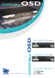
OSD U S E ADDERView & I N www.addertec.
About this manual AdderView OSD - Installation and Use Second edition (March 2002) Part No. ADD0034/2 (c) 2002 Adder Technology Ltd. All rights reserved. Whilst every precaution has been taken in the preparation of this manual, Adder Technology Ltd assumes no responsibility for errors or omissions. Neither is any liability assumed for damages resulting from the use of the information contained herein. We reserve the right to change the specifications, functions and circuitry of the product without notice.
Radio Frequency Energy Shielded cables must be used with this equipment to maintain compliance with radio frequency energy emission regulations and ensure a suitably high level of immunity to electromagnetic disturbances. European EMC directive 89/336/EEC This equipment has been tested and found to comply with the limits for a class B computing device in accordance with the specifications in the European standard EN55022.
Contents 1. Introduction .................................................................................... 5 1.1 Key features ........................................................................................... 5 1.2 Package contents (models AV4osd and AV8osd) ................................. 6 1.3 Rack mount kit contents (part code: AVrmk).......................................... 6 1.4 Remote controller contents (part code: AVremote) ................................ 6 1.5 Product information .
4. AdderView configuration options ................................................ 26 4.1 Screen saver time delay ........................................................................ 26 4.2 Autoscan lock on mode and delay time ................................................ 26 4.3 Mouse mode and mouse switching of channels .................................... 27 4.4 Keyboard hotkey combination ............................................................... 28 4.
1. Introduction Thank you for purchasing the AdderView OSD. Your AdderView is a high performance keyboard, monitor and mouse sharing device which supports a wide range of PC hardware and software platforms. 1.1 Key features Control multiple PCs from a single keyboard, monitor and mouse. On-screen menu allows computers to be selected by name. SmartBoot feature automatically boots all machines during power up. ‘Interface powered” operation – AdderView draws its power from the connected PCs.
Supports IBM ThinkPad ‘Y’ cables. Power and activity indication confirm correct operation. Standard cable connections make installation easy and inexpensive. All ports are active simultaneously – all PCs may all be booted at the same time. Robust metal case ensures good shielding and video quality. 19 inch rack mount kit available. Supports RS6000 computers. Optional power adapter can be used for ‘video only’ or cascade applications. 1.2 Package contents (models AV4osd and AV8osd) AdderView OSD.
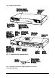
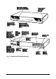
1.5 Product information Fig. 1 – AdderView OSD (model AV8osd) Fig.
Fig.
2. Installation 2.1 What you will need Cables to connect the AdderView to each of your PC keyboard, video and mouse ports. Cable specifications are given in appendix A. (You do not need to connect a mouse cable if you are not using the mouse). A monitor with a standard VGA/SVGA (15 pin) connector that will work when connected directly to each of your PCs. AdderView supports low and high resolution monitors. A standard AT or PS/2 style keyboard.
2.2 Mounting the AdderView The AdderView has been designed to be used either on a desktop or mounted in a 19 inch rack. If the AdderView is to be used on a desktop then you will need to stick the supplied self-adhesive rubber feet to the underside of the AdderView. If the AdderView is to be mounted in a 19 inch rack then you will need to fit the rack mounting brackets to the side of the AdderView. The 19 inch rack mounting brackets are supplied in the option rack mounting kit (part code: AVrmk) 2.
by the computers when they are switched on. 2.4 ‘Interface powered’ operation without the optional power adapter The AdderView draws its power from the connected computers via the keyboard cables. A single keyboard connection is normally sufficient to power the AdderView provided that the cable is no longer than 3 metres. If more than one computer is connected then the power will be intelligently drawn from all computers.
The options may be changed whilst the AdderView is in configure mode. You may enter configure mode at initial power on or whilst the AdderView is running: To enter configure mode at power on: Switch off all the attached PCs and the AdderView. Hold down the front panel key whilst powering on the AdderView. Remember that the AdderView draws its power from any attached PC via the keyboard cable and so will power itself on when the attached PC is switched on or when the optional power adapter is connected.
D1 - Menu appears with magenta / blue background and green highlight (default) D2 - Menu appears with red / blue background and green highlight D3 - Menu appears with blue / black background and light blue highlight D4 - Confirmation message remains on screen for standard time period (default) D5 - Confirmation message remains on screen for short time period D6 - Confirmation message remains on screen for extended time period L1 - AdderView locks on to active ports only during autoscanning (default) L2 - Ad
H1 - Hotkey combination is CTRL + ALT + command key (default) H2 - Hotkey combination is CTRL + SHIFT + command key H3 - Hotkey combination is ALT + SHIFT + command key H4 - Hotkey combination is RIGHT ALT + command key H5 - Hotkey combination is LEFT ALT + RIGHT ALT + command key H6 - Hotkey combination is LEFT CTRL + LEFT ALT + command key H7 - Hotkey combination is RIGHT CTRL + RIGHT ALT + command key H8 - No hotkey combination enabled F1 - Display firmware first digit F2 - Display firmware second digit
(although this is generally not advisable) - see section 2.9 for details. Keyboard and mouse mode switching - The AdderView keeps a log of the keyboard and mouse mode and resolution settings requested by each of the connected PCs. These settings are automatically restored to the shared keyboard and mouse when the AdderView channel is switched thus ensuring maximum software compatibility. The keyboard num, caps and scroll lock states are an obvious example of this process. 2.
plugged back in whilst the PC is running. Mouse movement can then only be restored by rebooting the PC. This is because the mouse drivers only setup and enable the mouse when the PC is initially booted. If you have switched off your AdderView or you are attempting to ‘hot plug’ it into a system that is already running, you may be able to restore lost mouse movement using the AdderView's mouse restoration functions.
3) To restore a PS/2 mouse connection press F 5 f Or, to restore an IntelliMouse connection press F 6 f 4) Exit from configure mode by typing E f 5) Test the mouse movement by moving the mouse a short distance.
3. Using the AdderView This section explains the general operation of the AdderView. We recommend that you read this section before starting to use the product. 3.1 Power on status At power on the AdderView selects PC number 1 and displays '1'. If a password has been set then ‘P’ will be displayed and the AdderView will remain locked until a valid password is entered.
3.2 Front panel key and remote controller The front panel key is used to select which channel is currently controlled by the shared keyboard, mouse and monitor ports. Pressing the key during normal operation will cause the next channel to be selected. The key can also be used to access the AdderView’s configuration mode (see section 2.6). To do this press the key and hold it down for 5 seconds until ‘C’ appears on the AdderView’s front panel display.
3.4 Keyboard hotkey control AdderView can be conveniently controlled by selecting channel, autoscan mode or security locking from the keyboard. All of the hotkey control commands are invoked by holding down the two hotkeys and then pressing a command key. By default, the two hotkeys are ‘CTRL’ and ‘ALT’, although other combinations can be selected by reconfiguring the hotkeys (see section 4.4).
The hotkey command are summarised below (note that the numbers on the numeric keypad do not form part of a valid hotkey) : ‘HOTKEYs’ and ‘1’ - selects channel 1 ‘HOTKEYs’ and ‘2’ - selects channel 2 ‘HOTKEYs’ and ‘3’ - selects channel 3 ‘HOTKEYs’ and ‘4’ - selects channel 4 ‘HOTKEYs’ and ‘5’ - selects channel 5 ‘HOTKEYs’ and ‘6’ - selects channel 6 ‘HOTKEYs’ and ‘7’ - selects channel 7 ‘HOTKEYs’ and ‘8’ - selects channel 8 (model AV8osd only) (model AV8osd only) (model AV8osd only) (model AV8osd only) ‘HO
To 'tab through' channels: press ba v release v press v release v press v release vba To activate the on-screen menu press baM release Mba 3.5 On-screen menu control AdderView can conveniently select a computer using the integral on-screen menu control. The menu is called up by pressing the two ‘HOTKEYs’ and ‘M’. When the menu is first called up, there will be no named computers listed. You must first enter the names and port numbers for computers which are to be selected from the menu.
Adding a computer to the menu list With the menu visible on the screen, press the INSERT key. This will cause a new Computer entry field to be inserted on the menu. This is highlighted in red with a cursor to indicate the text entry position. Type in a name up to 16 characters long. You can use upper/lower case, special and space characters. When completed press the RETURN key. The red highlighted area now moves into the Port entry field and you can enter the port number for the named Computer.
‘HOTKEYs’ and ‘M’ - calls the menu up onto the screen (even if no PC video exists) ‘INSERT’ - adds a computer entry AFTER the currently selected line ‘SHIFT’ and ‘INSERT’ - adds a computer entry BEFORE the currently selected line ‘DELETE’ - deletes the currently selected computer ‘SHIFT’ and ‘DELETE’ - edits the currently selected computer ‘RETURN’ - confirms an entry or selects a computer ‘ESC’ - quits from editing a line or quits from the menu ‘up arrow’ - moves up the menu by one line ‘down arrow’ - move
AdderViews as this avoids the need to use long hotkey sequences that may be hard to remember. Older style AdderView OSD (blue / white) front panels may be cascaded together with your new style AdderView OSD (black / silver front panel). For example, consider a situation where two AdderView units are connected together as shown below. To connect to the computer attached to port 3 on AdderView B the user would hold down the hotkey keys then press ‘2’ followed by ‘3’, whilst keeping the hotkey keys pressed.
4. AdderView configuration options All the options described in this section are entered in AdderView configure mode see section 2.6 for instructions on entering configure mode. 4.1 Screen saver time delay AdderView contains a programmable screen saver which will blank the display after the set time delay with no keyboard or mouse activity. Simply typing at the keyboard or moving the mouse will re-enable the display. The display will flash whilst the AdderView is in screen save mode.
L1 - AdderView only locks on to active ports during autoscanning (default) L2 - AdderView locks on to every port in turn during autoscanning L3 - AdderView powers on in autoscan mode and locks on to active ports only L4 - AdderView powers on in autoscan mode and locks on to all ports T1 - 2 seconds autoscan delay time before switching to next port (default) T2 - 5 seconds autoscan delay time before switching to next port T3 - 7 seconds autoscan delay time before switching to next port T4 - 10 seconds autosc
Microsoft IntelliMouse Logitech Pilot Mouse + Logitech MouseMan+ Genius NetMouse Genius NetMouse Pro Standard PS/2 and IntelliMouse compatible mice can be connected to the control port. You may configure your CPUs using Microsoft PS/2 or IntelliMouse drivers in any combination as required. The IntelliMouse features are supported on both PS/2 and RS232 CPU connections. When using PS/2 CPU connections, the AdderView will automatically configure itself to the type of mouse requested by the driver.
AdderView function. The left and right shift key combination is particularly suitable for extended keyboards where additional keys can be programmed to act as a combination of other keys. Such keyboards are supplied with many Gateway 2000 computers. Programming spare keys to trigger the hotkey combination allows channels to be selected via a single key stroke.
D1 - Menu appears with magenta / blue background and green highlight (default) D2 - Menu appears with red / blue background and green highlight D3 - Menu appears with blue / black background and light blue highlight D4 - Confirmation message remains on screen for standard time period (default) D5 - Confirmation message remains on screen for short time period D6 - Confirmation message remains on screen for extended time period 4.
4.8 Cascade query code The AdderViews use a special ‘query code’ to detect whether or not they are connected to another AdderView. By default your AdderView uses query code AD. SmartView (another range of keyboard / mouse / video switches from Adder Technology) units with firmware versions less than 1.09 used query code EF. This was found to conflict with a small number of other (rare) devices that used the same query code so an alternative query code was provided to ensure compatibility.
Appendix A. Cable and connector specifications IMPORTANT NOTE The maximum cable lengths supported vary widely between devices and cables. It may be possible to use cables that are longer than those specified below with certain PCs and peripherals but this cannot be guaranteed. If you experience problems try using shorter cables. A1. Keyboard, monitor and mouse to AdderView All of the shared devices plug directly into the relevant ports at the rear of the AdderView.
Keyboard and PS/2 mice - 6 pin mini-DIN male connector to 6 pin mini-DIN male connector with all lines connected straight through (1-1,2-2 etc.). If the PC has a 5pin DIN AT style keyboard connector you will need a PS/2 to AT keyboard adapter 6-pin mini-DIN female to 5-pin DIN male (readily available). For ‘self powered’ operation without the optional power adapter the cables should be no longer than 3 metres (see section 2.4 for more details).
Appendix B. Problem Solving Problem: Poor video quality with smearing fuzziness or ripple. Action: Use screened coaxial video cables to connect your devices to the AdderView. Problem: Mouse does not move cursor on screen. Action: Ensure that the mouse and computer are both connected to AdderView before power is connected and ensure that the AdderView is powered on before the attached computer.
the mouse to use a proprietary mouse data format not supported by the AdderView. If you have unplugged and re-connected a mouse to the AdderView then ensure that you reset it using the mouse reset function (see section 3.3). Problem: Mouse jumps around the screen after disconnecting the mouse cable or powering down the AdderView.
Notes AdderView Installation and Use Page 36
Notes AdderView Installation and Use Page 37
ADDERView OSD I N S TA L L AT I O N & U S E ADDER Technology Limited Technology House Trafalgar Way Bar Hill Cambridge CB3 8SQ • England Telephone: +44 (0) 1954 780044 Fax: +44 (0) 1954 780081 Email: sales@adder.com Web Site: www.adder.com AV-OSD-11.