
Datasheet

X2-10GB-LRM-AO
Cisco X2-LRM 10GB Module
1310nm, 220m, MMF, SC RoHS6
_______________________________________________________
Add-On Computer – 877-292-1701
Page 5 of 8
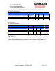
50 µm MMF 400 100
62.5 µm MMF 200 220
50 µm MMF 500 220
Fibre
Channel
50 µm MMF 2000 220
Notes:
1) Operating range as defined by IEEE and Fibre Channel standards. Longer reach possible
depending upon link implementation.
Environmental Performance
Operating case temperature: 0°C to +70°C
Operating humidity: 0% -95% RH non-condensing
Fibers and Connectors
The transponder has SC receptacles for both Tx and Rx. The transponder is designed
for multimode SC cables, 0° polished endface (PC).
70-pin Connector
The module interface connector is a 70-pin, printed circuit board edge connection with a 0.5
mm pitch. The appropriate mating connector for the customer PCB is a 70-pin SMT, dual
row, right angled, edge connector, 0.5 mm pitch (Tyco Electronics part number 1367337-1,
Molex part number 74441-0003 or equivalent).
Rail and Mechanical Mounting Requirements
The X2 rail system required to mount the X2 module is fully defined by the MSA. (Tyco
Electronics part number 1367608-1: designed for belly to belly applications; and 1367610-1,
designed for single sided board mount to fit into the standard host PCB footprint; or
equivalent). For further details please refer to vendor-supplied information.
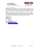
Regulatory Compliance
Feature Standard Comments
ESD: Electrostatic
Discharge to the
EIA/JESD22-A114-B (MIL-STD
883D
Class 1a (> 500 V)
Electrical Pins (HBM) Method 3015.7)