
User manual


A511 User Manual, Rev. 1.1 - 8 - 08/2007
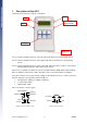
What do the various screens show?
The following figures show the various screens of the Analog Measurement Mode.
• Cabling 1 to Cabling 3
This screen shows the analog readings of all sensors connected to Port 1. The values
are displayed as percentages, where 100% = 2.5 Volts.
Figure 5: Cabling 1 to Cabling 3, no sensors attached
• Cabling 4 to Cabling 6
This screen shows the analog readings of all sensors connected to Port 2. The values
are displayed as percentages, where 100% = 2.5 Volts.
Figure 6: Cabling 4 to Cabling 6, no sensors attached
• Counter and digital inputs
Shows the sum of all pulses that were detected while a pulse output device (like a
rain gauge or a water meter) was connected to Port 1 and/or 2. It also shows
whether the digital input is active (“1”) or inactive (“0”). By default when connecting
a digital TTL status signal generator the display will show a “1” when a signal is
detected, and a “0”, when no signal is detected.
Figure 7: Counters 1 & 2 and digital inputs 1 & 2, nothing attached