
User manual


A511 User Manual, Rev. 1.1 - 3 - 08/2007
1. Description of the A511
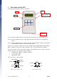
The image shows the major elements of the A511:
Port 1: a female 7-pin M9 connector on the left side of the device for testing analog sensors
Port 2: a female 7-pin M9 connector on the upper right side of the device for testing analog
sensors
Port 3: a female 5-pin M9 connector on the lower right side of the device used for a) checking or
changing SDI-12 addresses and b) testing solar panels
Connectors on the A511 are identical to those used with all Adcon A720, A723, A732 and A733
RTUs so all Adcon analog sensors and solar panels can be connected without any adapters.
The 7-pin connectors are used for analog readings as described in Section 4.1. These connectors
have the same pin-out as the RTU’s mentioned above:
• 3 analog inputs: Cabling 1, Cabling 2, Cabling 3
• 1 counter input “CNT”
• 1 digital input “DIG”
Pin out of the two connector types:
Cabling 1
Cabling 2
Cabling 3
Switched Battery
Digital I/O
Pulse
Counter
Ground
1
2
3
4
5
6
7
RxD
TxD
Ground
Ext. Power
Battery
1
2
3
4
5
Figure 1: Pin out of Ports 1 and 2 Figure 2: Pin out of Port 3
Port 1
Display
Foil Keypad
In the rear:
Battery Case
Port 3: Solar Panel &
SDI-12 Connector
Port 2