A511 Sensor & SolarPanel Test box This document describes the A511 Sensor & Solar Test box. It will facilitate rapid testing of Adcon compatible sensors and solar panels, and assist you in configuring SDI-12 sensors. A511 User Manual, Rev. 1.
Table of Content: 1. Description of the A511.......................................................................... 3 2. Switching the A511 ON and OFF............................................................ 4 3. Quick Start ............................................................................................. 4 4. 5. 3.1. How to test analog sensors........................................................................4 3.2. How to test the power consumption of Sensors .............
1.
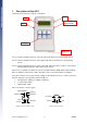
The A511 features two 7 pin testing ports. The outputs from each port are assigned different names to properly identify the readings. For uniformity we will therefore stick throughout this manual with the naming conventions as outlined in the following table: 7-pin connector on A511’s Port 1 (left) Port 2 (right) analog inputs Cabling 1, 2, 3 Cabling 4, 5, 6 counter inputs Counter1 Counter2 DIG1 DIG2 digital inputs 2.
3.2. How to test the power consumption of Sensors Testing for sensor power consumption is useful if you observe the RTU battery not charging normally. If the solar panel is located in a sunny location and oriented properly then it is possible that a defective sensor or short may cause excessive power draw. The A511 will let you test how many mA either analog or SDI-12 sensors are drawing • Turn the A511 on by pressing the “Menu ON” key. • Skip “Load last Menu settings?” by pushing the “F3” key.
Caution: Please check the specification of your SDI-12 device. Unless you are using an SDI-12 sensor with internal battery packs, it will be powered by the A511, and will therefore have to work with a supply voltage lower than specified in the SDI-12 standard (also see Section 5 – SDI-12 sensor specification). How to determine and change SDI-12 settings: • Switch the A511 ON by pushing the “Menu ON” key. • Skip “Load last Menu settings?” by pressing the “F3” key.
Figure 4: Load settings screen at startup sequence of A511 The A511 has two operating modes: • The Analog Measurement Mode • The SDI-12 Sensor Address Changer Mode. 4.1. Analog Measurement Mode This mode is for measuring analog sensors, which are connected to Ports 1 and 2, and for solar panels connected to Port 3. By default the A511 will start up in this mode. In order to see the readings of all three ports you need to toggle between the various screens as described below.
What do the various screens show? The following figures show the various screens of the Analog Measurement Mode. • Cabling 1 to Cabling 3 This screen shows the analog readings of all sensors connected to Port 1. The values are displayed as percentages, where 100% = 2.5 Volts. Figure 5: Cabling 1 to Cabling 3, no sensors attached • Cabling 4 to Cabling 6 This screen shows the analog readings of all sensors connected to Port 2. The values are displayed as percentages, where 100% = 2.5 Volts.
• Solar Panel Measurement This screen shows how much power (in V and mA) a solar panel generates. Voltage is measured using a load of 22 Ohm. Caution: The circuitry used for measuring solar power is not made to dissipate the power generated by long term testing. Please use this mode only for an instantaneous test of your solar panel! Leaving the solar panel test running continuously can build up heat and could damage the A511.
Customizing the Default Settings: To start the configuration Menu press the “Menu ON” key once. You will see the following three parameters on the screen of your A511: Figure 7: Analog Measurement option screen The top entry displays the status of the Permanent Power Supply setting, the centerline displays the status of the Measurement Mode, and the bottom entry displays the status of the Average Measurement Mode.
Combination of Modes You can certainly combine measurement methods. Setting Measurement Mode “Meas.” to “after 2s” and turning “AVG” ON will cause the A511 to power the sensor, warm it up for 1.8 seconds, take 10 readings, display their average, and turn the sensor off again. This cycle will then repeat after 3 seconds. Exit and Save the Configuration Menu To exit the configuration Menu press the “Menu ON” key once. The A511 will go back to the Analog Measurement Mode.
What do the various screens show? The following Figures will show you the various screens of the SDI-12 Address Change Mode. (Please note that values and settings are variable!) • SDI-12 Address Change screen Change and commit the new address by pushing the “F1”, “F2” and “F3” keys as outlined above. Figure 8: SDI address changer • SDI-12 Error Message screen Will show if an error occurred during the transaction with the sensor.
5. Technical Specifications Power Supply • A 9 volt block, alkaline or rechargeable battery Maximum ratings Inputs • 7 pin Ports 1 and 2: Input • max. unit Analog Inputs (Cablings 1 through 6) 3.3 V Counter Inputs (Counter1 and Counter 2) 3.3 V Digital Inputs (DIG1 and DIG2) 3.3 V max. unit Solar Panel Input 15 V Digital Input (SDI Data) 10 V 5-pin Port 3 Input Outputs (SBAT) The SBAT voltage depends on the current energy status of the battery.