
User guide

CHAPTER 2
System Setup
46
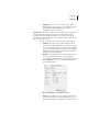
choose an appropriate sensor subclass by selecting
the appropriate icon.
Note: If you cannot find a suitable EUID for your sensor, contact
Adcon Telemetry.
• Display scale, min and max: type the default values
that will be displayed on a trend graph. In most
cases these values will be the same as for the
Conversion range (see below).
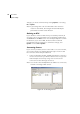
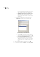
b. Specific entries for analog sensors are:
• Converter: select Linear or Tabular. A linear driver
needs only two values, a minimum and a maximum,
because all values in between are linearly computed
by the driver. If you have a nonlinear sensor, you
must either select one of the built-in tables or
provide your own table with 256 entries (equivalent
to an 8-bit accuracy)—in this later case you should
select other.... The table must be in the form of a
text file (similar to the original addVANTAGE 3 files),
which will be downloaded to the gateway via the
Configurator.
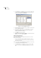
• Sensor type: for linear analog sensors, this defines if
the sensors deliver a voltage (0-2.5V) or a current (4-
20mA using the A502 current-to-voltage converter).
Note: The "4-20mA" setting assumes that you use the A502, which
converts a current of 4-20mA to a voltage of 0.4-2.0V. If you
want to use a different converter, you have to select "0-
2.5V" as sensor type and manually calculate the proper
“Conversion range" settings to reflect the physical values
the sensor would have for a converted voltage of 0 and 2.5V.
• Conversion range, min and max: the minimum and
maximum values delivered by your sensors. The
driver computes all the intermediate values from
these parameters (it automatically selects the
appropriate conversion equation for both 8-bit and
12-bit sensor values).
• Verifier: the driver can be instructed to check the
input values against some preset thresholds. If the
input values are outside the preset thresholds, an
invalid sensor value will be signaled.