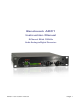
Benchmark ADC1 Instruction Manual 2-Channel 24-bit 192-kHz Audio Analog-to-Digital Converter ADC1 Instruction Manual Page 1
Federal Communications Commission (FCC) Notice (U.S. Only) NOTICE: This equipment has been tested and found to comply with the limits for a Class B digital device, pursuant to Part 15 of the FCC Rules. These limits are designed to provide reasonable protection against harmful interference in a residential installation.
Contents Overview 4 Features 6 Connections 7 Balanced Analog Line Inputs Clock Reference Input Digital Outputs AES/EBU XLR Output Optical Output SPDIF/AES BNC Main and Aux Outputs Word Clock Reference Output AC Power Entry Connector Fuse Holder Operation Mode Switch and Display Programming the Outputs Locking to an External Clock Source Selecting a Fixed Frequency Using the Internal Clock Source Reading Sample Rates off of the Mode Display Programming the Aux Output ADAT or AES/EBU on the Optical Out
Overview The ADC1 is a reference-quality, 2-channel 192-kHz 24-bit audio analog-to-digital converter featuring Benchmark’s UltraLock™ technology. The ADC1 is designed for maximum transparency. It is well suited for the most demanding applications in studios and mastering facilities. A rugged and compact half-wide 1 RU enclosure also makes the ADC1 an excellent choice for location recording, broadcast facilities, and mobile rigs.
The Auto mode allows the ADC1 to lock to an external clock reference. In Auto mode, the ADC1 will follow changes in sample rate, and/or changes in the type of reference signal (AES, SPDIF, word clock, or super clock). When a clock reference is not available, the Internal mode must be used, and a samplerate must be selected (44.1, 48, 88.2, 96, 176.4, or 192 kHz).
Features • • • • • • • • • • • • • • • • • • • • • • Two analog-to-digital conversion channels Two XLR balanced analog inputs providing high-performance over a 43 dB range -14 dBu to +29 dBu input sensitivity range (at 0 dBFS) Two 0 dB, 10dB, and 20 dB first-stage gain switches (1 per channel) Two 41-detent gain controls with a 20 dB range (1 per channel) Two 10-turn gain calibration controls with a 20 dB range (1 per channel) Benchmark 9-segment dual-range digital LED meters Sample Rate LED indicators Con
Connections Balanced Analog Line Inputs (XLR) Left Auxiliary Digital Output, BNC (AES) Aux 24 or 16-Bit Digital Output Right SPDIF, AES Analog Line In Main Digital Output, BNC (SPDIF/AES) AES/EBU AES, WC, SC Ref In ADAT/SPDI F WC Out Main 24-Bit Digital Outputs Main Digital Output, TOSLINK Optical (ADAT /SPDIF) Balanced Analog Line Inputs Left and Right balanced inputs use locking Neutrik™ gold-pin female XLR jacks. These inputs have a wide operating range.
Digital Outputs The ADC1 has four digital audio outputs: three Main Outputs and one Aux Output. designed to drive standard 4 Vpp AES signals into a 110 Ohm load. Use 110 Ohm digital cable when connecting this output to other devices. The use of analog audio cables may cause data transmission errors.
ADAT Optical Output Mode • • • • • Data Format = ADAT Word Length = 24 bits Sample Rate = 44.1 or 48 kHz Clock Source = Internal or external ADAT channel assignments: 1 = Left, 2 = Right, 3-8 = muted ADAT S/MUX2 Optical Output Mode • • • • • Data Format = ADAT Word Length = 24 bits Sample Rate = 88.
Word Clock Reference Output This output provides a Word Clock signal for use with downstream components. AC Power Entry Connector The AC power input uses a standard IEC type connector. Within the USA and Canada, the ADC1 ships with a power cord. In other locations, a location-specific IEC style power cord may be purchased from a local source (including a local Benchmark dealer). Fuse Holder The fuse holder is built into a drawer next to the IEC power connector.
Operation Mode Display Meter Switch Left First Stage Gain Mode Switch Meter Display Right First Stage Gain Left Gain Preset Right Gain Preset • Mode Switch and Display The ADC1 can be programmed to function in a variety of conversion modes, including sample rates, bit depths, and output formats, using internal and/or external clock sources. This programming is all done through the Mode Switch. The Mode Display shows the selected mode in a concise format.
Off = Internal Sync On = Locked to External Sync Flash = External Sync Selected but Not Locked The bottom left LED in the Mode Display is the Ext Indicator. It shows that the ADC1 is locked to an external clock source. If the Ext LED is off, then the ADC1 is set to operate at a fixed sample rate using the internal clock source. If the Ext LED is on, the ADC1 is locked to an external clock. When locked, the Mode Display will indicate the sample rate.
Programming the Aux Output The Aux Output can be programmed to mirror the Main Outputs (bit for bit), or it can provide an independent low-resolution copy of the converted signal, at an independent sample rate. Column three of the Mode Indicator displays the Aux Output mode setting. Note that no matter how the Aux Output is programmed it does not affect the Main Outputs in any way.
The red 0 LED indicates that a full-scale digital code has been reached and that digital clipping has occurred. Full-scale events as short as one digital sample, will light the 0 LED. Short single-sample digital clipping events are often audible, and all 0 dBFS events should be avoided. provides ultra-high performance at any gain setting between -1.3 dB and +42 dB. The higher gain settings will allow direct connections from many instrument pickups (no DI box required).
Down Position Rack Mounting To enable rack mounting, the front panel of the ADC1 has rack-mount holes that are machined to conform to standard rack mount dimensions. The width of the ADC1 panel is exactly ½ that of a standard 19” panel. The ADC1 is one rack unit high. Either ear of the ADC1 can be mounted directly to a standard 19” rack. A machined junction block connects the other ear to a ½ width blank panel, another ADC1, a DAC1, or other ½ width Benchmark products.
Using ADAT S/MUX Proper S/MUX Identification is a Must S/MUX2 allows recording 4 channels at 88.2 or 96 kHz using a standard 8-channel 44.1 or 48 kHz ADAT recorder. S/MUX4 allows recording 2 channels at 176.4 or 192 kHz using a standard 8-channel 44.1 or 48 kHz ADAT recorder. In either case it is important to identify S/MUX recordings so that they can be properly decoded upon playback. Failure to properly decode an S/MUX recording will add unwanted artifacts to the audio.
UltraLock™ … What is It? Accurate 24-bit audio conversion requires a very low-jitter conversion clock. Jitter can very easily turn a 24-bit converter into a 16bit converter (or worse). There is no point in buying a 24-bit converter if clock jitter has not been adequately addressed. Jitter is present on every digital audio interface. This type of jitter is known as interface jitter and it is present even in the most carefully designed audio systems.
How does conversion clock jitter degrade converter performance? Problem #1 Jitter phase modulates the audio signal. This modulation creates sidebands (unwanted tones) above and below every tone in the audio signal. Worse yet, these sidebands are often widely separated from the tones in the original signal. Jitter-induced sidebands are not musical in nature because they are not harmonically related to the original audio.
Is it possible to eliminate all of the effects of jitter in an entire digital audio system? Interface jitter will accumulate throughout even the most carefully designed digital audio system. Fortunately, interface jitter can only degrade digital audio if it affects the sampling circuit in an analog-to-digital or analog-todigital converter. Any attempt to cure jitter outside of an ADC or DAC will prove expensive and, at best, will only partially reduce jitter-induced artifacts.
Performance Frequency Response The above graphs show the frequency response of the ADC1 when it is operating at a 192-kHz sample rate. Note that the amplitude response is down by less than 0.05 dB at 10 Hz and 80 kHz. The bass response extends well below the 10-Hz limitation of the measurement equipment, and the high-frequency analog response extends well above the 96 kHz bandwidth of 192 kHz digital audio.
Inter-Channel Phase Response This graph shows that the differential phase is significantly better than ± 0.25º from 10 Hz to 20 kHz.
THD+N vs. Level, 1 KHz w/20 kHz LPF unweighted Below –4 dBFS, distortion is lower than the noise floor of the converter. Above –3 dBFS, distortion reaches a maximum value of only –107 dBFS.
32K B-H FFT, Idle Channel Noise The above graph demonstrates that the ADC1 is free from idle tones and clock crosstalk. The highest spurious tone measures –128 dBFS and is AC line related hum. The highest non-line related tone measures –135 dBFS.
32K B-H FFT, -3 dBFS, 1 KHz The above FFT plot shows that the ADC1 has very little harmonic distortion. Distortion is exceptionally low and is dominated by 2nd harmonic distortion. Note the near absence of spurious tones.
32K B-H FFT, -3 dBFS, 10 KHz The above FFT plot shows that the ADC1 is free from jitter-induced sidebands. Any jitter present at the conversion sampling circuit would produce sidebands equally spaced above and below the 10 kHz test tone. The tone at 20 kHz is due to second harmonic distortion, and measures almost 120 dB below full scale. Note the near absence of spurious tones.
Specifications Analog Audio Inputs Number of Inputs (balanced) 2 Connector Gold-Pin Neutrik™ female XLR Impedance 200 kΩ Sensitivity -14dBu to +29 dBu (at 0 dBFS) Clock Reference Input Format Auto-detect AES/EBU, Word Clock, and Super Clock (256x) Impedance 75 Ω Sensitivity 150 mV AES 200 mV Word Clock 750 mV Super Clock Transformer Coupled Yes DC Blocking Capacitors Yes Transient and Over-Voltage Protection Yes Jitter Attenuation Method Benchmark UltraLock™ Worldclock Reference Output
Digital Audio Outputs Number of Digital Outputs 1 1 1 1 Connectors Gold-Pin Neutrik™ male XLR Number of Audio Channels 2 Main Output Word Length 24 bits Main Output Sample Frequencies 44.1, 48, 88.2, 176.4, or 192 kHz Aux Output Word Length 16 or 24 bits Aux Output Sample Frequencies 44.1, 48, 88.2, 176.4, or 192 kHz at 24 bits 44.
Audio Performance Fs = 44.1 to 192 kHz, 20 to 20 kHz BW, 1 kHz test tone, 0 dBFS = +24 dBu (unless noted) SNR – A-Weighted, 0 dBFS = +8 to +29 dBu 121 dB SNR – Unweighted, 0 dBFS = +8 to +29 dBu 119 dB SNR – A-Weighted at max gain, 0 dBFS = -14 dBu 108 dB THD+N, 1 kHz at –1 dBFS -102 dBFS, -101 dB, 0.00089% THD+N, 1 kHz at –3 dBFS -107 dBFS, -104 dB, 0.00063% THD+N, 20 to 20 kHz test tone at –3 dBFS -106 dBFS, -103 dB, 0.
Jitter Tolerance (With no Measurable Change in Performance) >12.75 UI sine, 100 Hz to 10 kHz > 3.5 UI sine at 20 kHz > 1.2 UI sine at 40 kHz > 0.4 UI sine at 80 kHz > 0.29 UI sine at 90 kHz > 0.25 UI sine above 160 kHz Maximum Amplitude of Jitter Induced Sidebands < -134 dB (measurement limit) (10 kHz 0 dBFS test tone, 12.
AC Power Requirements Input Operating Voltage Range (VAC RMS) 110 V setting – 95 V min, 140 V max 220 V setting – 190 V min, 285 V max Frequency 50-60 Hz Power 16 Watts Idle 16 Watts Typical Program 20 Watts Maximum Fuses 5 x 20 mm (2 required) 110 V setting – 0.5 A 250 V Slo-Blo® Type 220 V setting – 0.5 A 250 V Slo-Blo® Type Dimensions Form Factor ½ Rack Wide, 1 RU High Depth behind front panel 8.5” (216 mm) Overall depth including connectors but without power cord or BNC-to-RCA adapter 9.
ADC1 Instruction Manual Page 31
Warranty Information Benchmark 1 Year Warranty The Benchmark 1 Year Warranty Benchmark Media Systems, Inc. warrants its products to be free from defects in material and workmanship under normal use and service for a period of one (1) year from the date of delivery. This warranty extends only to the original purchaser. This warranty does not apply to fuses, lamps, batteries, or any products or parts that have been subjected to misuse, neglect, accident, modification, or abnormal operating conditions.
Benchmark Extended Warranty The Benchmark Extended 5* Year Warranty Benchmark Media Systems, Inc. optionally extends the standard one (1) year warranty to a period of five (5)* years from the date of delivery. *For the extended warranty to become effective, the original purchaser must register the product at the time of purchase either by way of the prepaid registration card or through the product registration section of the Benchmark Media Systems, Inc. website.
Copyright © 2005 Benchmark Media Systems, Inc. All rights reserved. Benchmark Media Systems, Inc. 5925 Court Street Road Syracuse, NY 13206-1707 USA +1-315 437-6300, FAX +1-315-437-8119 http://www.benchmarkmedia.