ADCP-80-575 Issue 2 December 2006 PowerWorx® Power Distribution Products Select Series™ Fuse Platform (With Enhanced KLM Fuses) User Manual 18858-A 1388844 Rev B
ADCP-80-575 • Issue 2 • December 2006 • Preface COPYRIGHT © 2006, ADC Telecommunications, Inc. All Rights Reserved Printed in the U.S.A. REVISION HISTORY ISSUE DATE 1 11/2006 REASON FOR CHANGE Original. 2 12/2006 Figure 3 block diagram changed to show dual bus; minor changes in section 1.8 and table 1. TRADEMARK INFORMATION PowerWorx is a registered trademark of ADC Telecommunications, Inc. ADC is a trademark of ADC Telecommunications, Inc.
ADCP-80-575 • Issue 2 • December 2006 • Preface TABLE OF CONTENTS Content Page About This Manual . . . . . . . . . . . . . . . . . . . . . . . . . . . . . . . . . . . . . . . . . . . . . . . . . . . . . . . . . . . . . . . . . . . . . . . . . . . v Standards Certification . . . . . . . . . . . . . . . . . . . . . . . . . . . . . . . . . . . . . . . . . . . . . . . . . . . . . . . . . . . . . . . . . . . . . . . . v Admonishments . . . . . . . . . . . . . . . . . . . . . . . . . . . . . . . . . . . . . .
ADCP-80-575 • Issue 2 • December 2006 • Preface TABLE OF CONTENTS Content Page 4.6 Connecting Input Power . . . . . . . . . . . . . . . . . . . . . . . . . . . . . . . . . . . . . . . . . . . . . . . . . . . . . . . . . . . . 23 4.7 Installing Protective Covers . . . . . . . . . . . . . . . . . . . . . . . . . . . . . . . . . . . . . . . . . . . . . . . . . . . . . . . . . 25 4.8 Installing GMT Fuse Designation Pins . . . . . . . . . . . . . . . . . . . . . . . . . . . . . . . . . . . . . . . . . .
ADCP-80-575 • Issue 2 • December 2006 • Preface ABOUT THIS MANUAL This manual describes the PowerWorx® Select Series™ Fuse Platform and provides installation, operation, maintenance, and testing procedures. The Select Series™ Fuse Platform is available with various types of fuses including TPA, KLM, and GMT fuses. Two types of fuses can be combined within the same platform, if required.
ADCP-80-575 • Issue 2 • December 2006 • Preface Warning: Wet conditions increase the potential for receiving an electrical shock when installing or using electrically-powered equipment. To prevent electrical shock, never install or use electrical equipment in a wet location or during a lightning storm. Page vi © 2006, ADC Telecommunications, Inc.
ADCP-80-575 • Issue 2 • December 2006 1 PRODUCT DESCRIPTION This section describes the PowerWorx Select Series Fuse Platform. 1.1 Product Functions and Features The Select Series Fuse Platform, shown on the front cover of this manual, supplies protected dc power to the –24 Vdc or –48 Vdc equipment typically installed in a central office, multimedia headend, remote site, Controlled Environmental Vault (CEV), or other restricted locations.
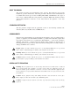
ADCP-80-575 • Issue 2 • December 2006 UL/CSA/CE LABEL BUS A POWER ON INDICATOR BUS B POWER ON (GREEN LED) INDICATOR (GREEN LED) BUS A BUS A KLM/KTK KLM/KTK FUSE HOLDERS FUSE ALARM INDICATOR (TYPICAL) BUS A GMT FUSE ALARM INDICATOR BUS A GMT FUSE HOLDER (4 POSITION) BUS B GMT FUSE ALARM INDICATOR BUS B KLM/KTK FUSE ALARM BUS B KLM/KTK INDICATOR (TYPICAL) FUSE HOLDER BUS B GMT FUSE HOLDER (4 POSITION) FRONT VIEW DESIGNATION CARD AND CARD HOLDER CHASSIS GROUND STUDS BUS B POWER INPUT TERMINALS BUS B
ADCP-80-575 • Issue 2 • December 2006 Warning: Use of one bus only on a dual bus panel will result in false alarms for the unused bus. Power is required on both buses on a dual bus panel for normal operation. Depending on customer order, the fuse platform may have one fuse type alone, or GMT fuses in combination with one other fuse type (KLM or TPA).
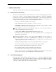
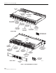
ADCP-80-575 • Issue 2 • December 2006 1.4 Packaged Hardware The fuse platform is shipped with hardware components (shown in Figure 2) that are packaged separately and enclosed in the same carton. The packaged hardware components include the following items: • Two sets of mounting brackets (for 19-inch or 23-inch rack mounting)—Used to mount the panel on the equipment rack. • 5/16-inch long, Phillips drive, 8-32 flat-head thread-forming screws (8)—Used to secure the mounting brackets to the panel.
ADCP-80-575 • Issue 2 • December 2006 REAR COVER FOR OUTPUT POWER TERMINAL BLOCKS, ALARM TERMINALS, AND CHASSIS GROUND TERMINALS REAR COVERS FOR INPUT POWER TERMINAL BLOCKS #10 RING TERMINALS FOR 12-10 AWG WIRE (GROUNDING) 5/16-INCH (7.936 MM) 8-32 FLAT-HEAD SCREWS 19-INCH RACK MOUNTING BRACKETS 3/8-INCH (9.
ADCP-80-575 • Issue 2 • December 2006 1.5 Accessories The following accessories are available for the fuse platform: • Standard size GMT, KLM, and TPA type fuses • GMT colored fuse-value designation pins (rivets) • Cable management bar kits • GMT fuse pullers • Two-hole compression connector lugs for input power connections • Lug terminals to connect #10 AWG wire to earth ground • GMT fuse value designation pin holders • Fuse value designation card holder kits 1.
ADCP-80-575 • Issue 2 • December 2006 KLM GMT BATT BATT RTN RTN BATT RTN 1 1 2 2 3 3 4 4 RED RED KLM GMT GREEN ALARM MONITOR POWER A NO C NC AUDIO VISUAL GREEN ALARM MONITOR REMOTE POWER B ALARM RED RED KLM BATT RTN BATT GMT RTN BATT RTN 1 1 2 2 3 3 4 4 20827-A Figure 3. Block Diagram of GMT-KLM Bus – Initially, if there is no input power to the A or B bus, or if there is no fuse placed in the KLM fuse holder, the LED will be unlit (no green or red light).
ADCP-80-575 • Issue 2 • December 2006 – An alarm can be cleared in any KLM fuse position by installing a new fuse and removing it when the green LED flashes. When the alarm is cleared, the LED changes from red to unlit (no red light or green light). The LED remains unlit until a good fuse in installed, whereupon it turns green. For the alarm clearing procedure, refer to Section 6.1 on Page 28. The maximum current capacity of each power bus circuit is 100 Amps.
ADCP-80-575 • Issue 2 • December 2006 Each input terminal block includes two pairs of 0.25-inch studs that are used for connecting the BATT (battery –) and RTN (return +) input power cables. Each pair of studs is mounted on 0.625 inch centers and accepts various size 2-hole compression lugs. The maximum lug width is 0.62 inches. Compression lugs for various sizes AWG wire are available as accessory items. Nuts with captive washers are included to secure the compression lugs to the studs.
ADCP-80-575 • Issue 2 • December 2006 1.12 Ground Connectors Two #10 studs (with nuts) are provided for grounding the fuse platform chassis. The studs are mounted on 0.625 inch (15.875 mm) centers. Two crimp ring lug terminals for two #10 AWG wires are provided with each fuse platform. The fuse platform may be grounded using only one stud. 1.
ADCP-80-575 • Issue 2 • December 2006 alarm indicator is off when all fuses in the fuse holder module are operational. Loss of power to a bus will not cause the fuse alarm indicators corresponding to that bus to be lighted. For GMT fuses, there are four or ten fuses per fuse holder with a single fuse alarm indicator for the entire set of fuses. For TPA fuses, there is one fuse holder per fuse and, therefore, a fuse alarm indicator for each fuse.
ADCP-80-575 • Issue 2 • December 2006 1.18 Voltage Designation Label A voltage designation label, shown in Figure 5, is provided with the fuse platform. The label may be filled out with the actual voltage present on the buses and placed on the fuse platform. The voltage designation label has a pressure sensitive adhesive backing for attachment. 0.38 IN. (0.96 CM) 14228-A 1.00 IN. (2.54 CM) Figure 5. Voltage Designation Label 1.
ADCP-80-575 • Issue 2 • December 2006 inches (4.45 cm) of air space (one rack space) must be provided above and below the fuse platform to allow air to circulate freely. 1.22 Protective Cover A smoked plastic protective cover is mounted over the input power connectors, the output power connectors, the chassis ground terminals, and the external alarm contact connections. To access the connectors and terminals, loosen (do not remove) the four screws. 1.
ADCP-80-575 • Issue 2 • December 2006 2 UNPACKING AND INSPECTION Before starting the installation, always open the shipping boxes and verify that all parts have been received and that no shipping damage has occurred. Use the following procedure to unpack and inspect the fuse platform: 1. Open the shipping carton and carefully unpack the fuse platform from the protective packaging. 2. Check the panel for broken or missing parts.
ADCP-80-575 • Issue 2 • December 2006 3.3 Materials Required The following materials are required to install the fuse platform: • • • • • • #2 AWG insulated copper wire for input power wires 2-hole compression lugs for #2 AWG wire (0.
ADCP-80-575 • Issue 2 • December 2006 3. Re-install the fuse holder (with working fuse). 4. Connect one test probe to the BATT (–) terminal on the input power terminal block. 5. Connect the other test probe to the BATT terminal on the output power terminal block. 6. Verify that continuity exists between the specified terminals. 7. Repeat the test procedure for the second fuse type, if present. 8. Repeat the test procedure for the second power bus, if present.
ADCP-80-575 • Issue 2 • December 2006 4. Repeat the test procedure for second fuse type, if present. 5. Repeat the test procedure for the second power bus, if present. TEST 4- POWER BUS B: VERIFY THAT CONTINUITY EXISTS BETWEEN INPUT AND TYPE 1 FUSED OUTPUT RTN TERMINALS TEST 4- POWER BUS A: VERIFY THAT CONTINUITY EXISTS BETWEEN INPUT AND TYPE 1 FUSED OUTPUT RTN TERMINALS 18874-A Figure 10.
ADCP-80-575 • Issue 2 • December 2006 Caution: This equipment employs electrical voltage and amperage levels which may be considered an electrical hazard. Care should be exercised to assure that only qualified personnel are allowed to install, operate, maintain, or otherwise come in contact with this equipment when the fuse platform is energized. Only insulated tools should be used on energized elements of the fuse platform.
ADCP-80-575 • Issue 2 • December 2006 4.2 Mounting Fuse Platform on Rack The fuse platform can be mounted in either a 19- or 23-inch (48.26 or 58.42 cm) wide rack. Two sets of mounting brackets, one set for 19-inch racks and one set for 23-inch racks, are provided with the fuse platform. Eight 5/16-inch (7.936 mm) long, thread-forming, Phillips-drive, 8-32 flat-head screws are provided for attaching the mounting brackets to the panel. Four 3/8-inch (9.
ADCP-80-575 • Issue 2 • December 2006 4. Place the fuse platform in the specified mounting space within the rack. 5. Secure the fuse platform to the equipment rack as shown in Figure 14 using the four 3/8inch (9.53 mm) long pan-head screws and flat washers provided. Caution: Do not use any hardware other than the hardware supplied with the fuse platform. TIGHTEN MOUNTING SCREWS TO 27 POUND-FORCE INCHES (3.
ADCP-80-575 • Issue 2 • December 2006 6. Locate the C GND (chassis ground) studs at the rear of the panel as shown in Figure 15. DETAIL DRAWING OF GROUNDING WIRE CONNECTION 18868-A TIGHTEN STUD NUT TO 23 POUND-FORCE INCHES (2.6 NEWTON METERS) OF TORQUE Figure 15. Chassis Ground Connections 4.
ADCP-80-575 • Issue 2 • December 2006 SCREW-DOWN BARRIER TERMINAL STRIP CONNECT TO CORRESPONDING ALARM CONNECTORS CONNECT TO REMOTE ALARMS CONNECT TO REMOTE ALARMS WIRE-WRAP PIN TERMINAL BLOCK CONNECT TO CORRESPONDING ALARM CONNECTORS CONNECT TO AUDIO ALARMS CONNECT TO VISUAL ALARMS CONNECT TO REMOTE ALARMS 17056-A Figure 16. Alarm Contact Connections 4.5 Connecting Output Power Output power is supplied to the equipment through screw-down barrier terminal strips located on the rear of the chassis.
ADCP-80-575 • Issue 2 • December 2006 POWER FEED TERMINALS DETAIL DRAWING OF OUTPUT TERMINAL BLOCK CONNECTIONS TIGHTEN TERMINAL SCREWS TO 15 POUND-FORCE INCHES (1.7 NEWTON METERS) OF TORQUE POWER RETURN TERMINALS 18869-A BUS A GMT FUSED POWER OUTPUT TERMINALS BUS A KLM/KTK FUSED POWER OUTPUT TERMINALS Figure 17. Output Power Connections Caution: Connecting the equipment to the wrong circuit may cause damage to the equipment or the fuse platform.
ADCP-80-575 • Issue 2 • December 2006 Warning: Use of one bus only on a dual bus panel will result in false alarms for the unused bus. Power is required on both buses on a dual bus panel for normal operation. Caution: Connect only the input voltage wire [the wire labeled BATTERY or BATT, or labeled with the negative (–) voltage polarity and/or the voltage value] to the connector on the fuse platform labeled BATTERY.
ADCP-80-575 • Issue 2 • December 2006 b. Return wires: Connect to RTN (+) terminals on the A and B input power terminal blocks. 9. Use a torque wrench (with a 7/16-inch socket) to tighten the input power terminal block nuts to 32 pound-force inches (3.6 Newton meters) of torque. 10. Route the free end of each input power cable to the office battery source. 18870-A TIGHTEN INPUT TERMINAL NUTS TO 32 POUND FORCE INCHES (3.6 NEWTON METERS) OF TORQUE Figure 19. Input Power Connections 11.
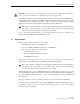
ADCP-80-575 • Issue 2 • December 2006 4.8 Installing GMT Fuse Designation Pins Color-coded fuse designation pins (accessory item) are available for GMT fuses. The pin color corresponds to the color of the fuse indicator. Insert the appropriate color-coded pins (accessory item) into the corresponding holes in each GMT fuse holder as required. 4.
ADCP-80-575 • Issue 2 • December 2006 6. Using a multimeter set to measure DC voltage, measure the voltage between each input power (RTN) terminal and chassis ground. The voltage level should be less than 2.0 Vdc. 7. If the voltage is much higher, and reads out in the –21 to –60 Vdc range, the input leads are probably reversed. If this appears to be true, power down the panel. Disconnect the negative (BATT) and positive (RTN) input lugs and switch them around.
ADCP-80-575 • Issue 2 • December 2006 To test the KLM fuse alarm indicator, use the following procedure: 1. With the fuse platform powered and no KLM fuses installed, verify that no fuse alarm LEDs are lit (no red or green light). Verify that the fuse alarm relay indicates an open circuit between the NO contact and the C contact at the fuse alarm contacts. 2. Insert a known good KLM fuse in each position to be used, one at a time, and verify that the corresponding fuse alarm LED turns green.
ADCP-80-575 • Issue 2 • December 2006 2. Wait about ten seconds until the green LED starts to blink off and on, which it will do five times. 3. While the LED is blinking, remove the good fuse just installed. If the fuse is removed during this flashing, the fuse position will go to a non-used status and no alarms will be present. The LED will turn off and remain unlit until a new fuse is installed. 4. Return the removed fuse to its original location.
ADCP-80-575 • Issue 2 • December 2006 8 CUSTOMER INFORMATION AND ASSISTANCE PHONE: U.S.A.
ADCP-80-575 • Issue 2 • December 2006 APPENDIX A: ALLOWABLE AMPACITIES OF INSULATED CONDUCTORS This appendix provides guidelines for selecting AWG wire size based on the temperature rating of the conductor and the anticipated load. The information contained is from Table 310-16 of the National Electrical Code document, ANSI/NPFA 70 (1978). Note: Information for aluminum conductors has been omitted from the table here because copper conductors only are recommended for use with the ADC panel.
ADCP-80-575 • Issue 2 • December 2006 Table 310-16 (NEC): Allowable Ampacities of Insulated Conductors, Rated O Through 2000 Volts, 60° to 90°C (140° to 194°F), Not More Than Three Current-Carrying Conductors in Raceway or Cable or Earth (Directly Buried), Based on Ambient Temperature of 30°C (86°F) SIZE AWG KCMIL TEMPERATURE RATING OF CONDUCTOR 60°C 60°C (114°F) (114°F) TYPES TBS, SA, SIS, FEP*, FEPB*, MI, RHH*, RHW-2, THHN*, TYPES THHW*, THW-2*, FEPW*, THWN-2*, RH*, RHW*, USE-2, THHW*, XHH, THW*, XHHW*
www.adc.