ADCP-80-570 Issue 2 March 2006 PowerWorx® Power Distribution Products Circuit Breaker Panel With Reset Switch User Manual 20629-A 1361499 Rev A
ADCP-80-570 • Issue 2 • March 2006 • Preface COPYRIGHT © 2006, ADC Telecommunications, Inc. All Rights Reserved Printed in the U.S.A. REVISION HISTORY ISSUE DATE 1 8/2005 REASON FOR CHANGE Original. 2 3/2006 Wire colors corrected on Page 28. TRADEMARK INFORMATION ADC and PowerWorx are registered trademarks of ADC Telecommunications, Inc. DISCLAIMER OF LIABILITY Contents herein are current as of the date of publication. ADC reserves the right to change the contents without prior notice.
ADCP-80-570 • Issue 2 • March 2006 • Preface TABLE OF CONTENTS Content Page About This Manual . . . . . . . . . . . . . . . . . . . . . . . . . . . . . . . . . . . . . . . . . . . . . . . . . . . . . . . . . . . . . . . . . . . . . . . . . . . v Standard Certification . . . . . . . . . . . . . . . . . . . . . . . . . . . . . . . . . . . . . . . . . . . . . . . . . . . . . . . . . . . . . . . . . . . . . . . . . v Admonishments . . . . . . . . . . . . . . . . . . . . . . . . . . . . . . . . . . . . . . .
ADCP-80-570 • Issue 2 • March 2006 • Preface TABLE OF CONTENTS Content Page 4.10 Connecting Output. . . . . . . . . . . . . . . . . . . . . . . . . . . . . . . . . . . . . . . . . . . . . . . . . . . . . . . . . . . . . . . . 20 4.11 Connecting Input. . . . . . . . . . . . . . . . . . . . . . . . . . . . . . . . . . . . . . . . . . . . . . . . . . . . . . . . . . . . . . . . . 21 4.12 Installing Protective Covers . . . . . . . . . . . . . . . . . . . . . . . . . . . . . . . . . . . . . . . . . . . . . .
ADCP-80-570 • Issue 2 • March 2006 • Preface ABOUT THIS MANUAL This manual describes the PowerWorx Circuit Breaker Panel With Reset Switch, and provides all information required to install, test, and operate this product. STANDARD CERTIFICATION The panel conforms to the applicable requirements of the following: UL/CSA/EN 60950, FCC Part 15, CISPR 22, and CISPR 24. ADMONISHMENTS Important safety admonishments are used throughout this manual to warn of possible hazards to persons or equipment.
ADCP-80-570 • Issue 2 • March 2006 • Preface Warning: To prevent the system from overheating, do not operate it in an area that exceeds the maximum recommended ambient temperature of 55º C. Warning: Stability hazard. The rack stabilizing mechanism must be in place, or the rack must be bolted to the floor before you slide the unit out for servicing. Failure to stabilize the rack can cause the rack to tip over. Warning: Suitable for mounting on concrete or other non-combustible surface only.
ADCP-80-570 • Issue 2 • March 2006 1 PRODUCT DESCRIPTION This section describes the PowerWorx Circuit Breaker Panel With Reset Switch.
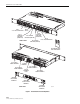
ADCP-80-570 • Issue 2 • March 2006 BUS A 1 TO 7 CIRCUIT BREAKERS BUS A POWER-ON INDICATOR (GREEN LED) RESET SWITCH BUS A ALARM INDICATOR (RED LED) BUS B POWER-ON INDICATOR (GREEN LED) BUS B 1 TO 7 CIRCUIT BREAKERS FRONT VIEW BUS B ALARM INDICATOR (RED LED) DESIGNATION CARD AND CARD HOLDER BUS B INPUT POWER TERMINALS ALARM TERMINALS BUS B OUTPUT POWER TERMINALS BUS A OUTPUT POWER TERMINALS CHASSIS GROUNDING STUDS BUS A INPUT POWER TERMINALS COVER FOR INPUT POWER TERMINALS COVER FOR OUTPUT POWER
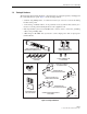
ADCP-80-570 • Issue 2 • March 2006 1.3 Packaged Hardware The shipped product includes hardware components that are packaged separately and shipped in the carton with the basic panel. Figure 2 shows the shipped items: • 5/16-inch long, Phillips drive, 8-32 flat-head screws (8)—Used to secure the mounting brackets to the panel. • 3/8-inch long, combination drive, 12-24 pan-head screws (4) and #12 flat washers (4)— Used to secure the panel mounting brackets to the equipment rack.
ADCP-80-570 • Issue 2 • March 2006 • Rear protective input terminal covers (2) and output/alarm terminal cover (1)—Used to prevent accidental contact with the alarm and power terminals. • #6-32 Screws (4)—Used to fasten output/alarm terminal cover to rear of panel chassis. • Designation card and card holder (1)—Used to record information about the protected equipment. Cards and clear cover insert into the card holder. • Voltage label (1)—Used to indicate whether the input voltage is –48 or –24 Vdc. 1.
ADCP-80-570 • Issue 2 • March 2006 Each of the power buses supports seven circuit breaker positions including two 10 Amp circuit breaker positions and five 5 Amp circuit breaker positions giving a total capacity per bus of 45 Amps. When a circuit breaker trips, the input power bus is disconnected from the corresponding output circuit. 1.5 Input Voltage The dual bus circuit breaker panel can accommodate either –24 Vdc on both buses or –48 Vdc on both buses.
ADCP-80-570 • Issue 2 • March 2006 The individual terminals are on 0.375 inch (9.525 mm) centers with a distance between barriers of 0.32 inch (81.3 mm). The terminals can accept a variety of wire sizes up to #12 AWG with crimp-on spade lug connectors or wires in sizes from #12 AWG to #22 AWG with the insulation stripped back. The connectors or wires are inserted under the screws in the terminal strip, and the screws are tightened down.
ADCP-80-570 • Issue 2 • March 2006 1.12 Breaker Alarm Indicators For each bus, the circuit breaker panel has one visual Breaker Alarm indicator (red LED) mounted on the front of the panel. The breaker alarm indicator lights if any circuit breaker on the corresponding bus trips off. Loss of power to either bus will cause the circuit breaker alarm indicator for the corresponding bus to be off. 1.
ADCP-80-570 • Issue 2 • March 2006 The card should be filled out with circuit information for each of the circuit breakers installed in the panel and inserted in the card holder. The card holder has a pressure sensitive adhesive backing for attachment. 1.60 IN. (4.06 CM) 2.36 IN. (5.99 CM) 16753-A 10 POSITION A AND B CARD Figure 4. Circuit Breaker Designation Card 1.17 Voltage Designation Label A voltage designation label such as shown in Figure 5 is provided with the circuit breaker panel.
ADCP-80-570 • Issue 2 • March 2006 Note: The panel requires one open rack space above the chassis and one open rack space below the chassis for heat dissipation. 1.20 Protective Covers The panel has three protective covers mounted on the rear side of the panel. Two of these are snap-on covers that mount over the input power connectors. A third, larger cover mounts over the output power connectors and the external alarm connections. This cover is secured with four 6-32 screws provided with the panel.
ADCP-80-570 • Issue 2 • March 2006 1.22 Specifications Table 2 lists specifications for the circuit breaker panel. Table 2. Circuit Breaker Panel Specifications PARAMETER SPECIFICATION REMARKS Physical Weight 12 pounds (5.45 kilograms) Dimensions (HxWxD) 1.75 x 17.13 x 11.0 inches (44 x 435 x 280 mm) Color Putty white Rack mounting 19- or 23-inch (EIA or WECO hole spacing) Flush or with a recess of 1, 2, 3, or 4 inches (25.4, 50.8, 76.2, or 101.
ADCP-80-570 • Issue 2 • March 2006 Table 2. Circuit Breaker Panel Specifications, continued PARAMETER SPECIFICATION REMARKS Torque Mounting bracket chassis screws 15 pound-force inches 1.7 Newton meters Mounting bracket rack screws 27 pound-force inches 3.1 Newton meters Alarm contacts 9 pound-force-inches 1 Newton meter Input power terminal nuts 32 pound-force inches max. 3.5 Newton meters max. Output power terminal screws 12 pound-force inches max. 1.3 Newton meters max.
ADCP-80-570 • Issue 2 • March 2006 2 ACCESSORIES The following accessories for the PowerWorx circuit breaker panel are available: • Cable management bar with mounting screws. Provides cable tie points. Installed at rear of circuit breaker panel by fastening ends of bar to both sides of the panel; • Various sizes of two-hole compression lugs for input power connection. • Lug terminals to connect #10 AWG wire to earth ground. • Circuit breaker designation card kit.
ADCP-80-570 • Issue 2 • March 2006 4.1 Installation Tools Required The following tools are required to install the circuit breaker panel: • Screwdrivers (both Phillips and flatblade) • Torque screwdriver calibrated in pound-force inches or Newton meters • 3/8-inch and 7/16-inch bits (for torque screwdriver) • Wire cutter • Wire stripper • Compression lug crimper • Multimeter • Heat gun 4.
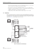
ADCP-80-570 • Issue 2 • March 2006 Test 1: Input Battery to Input Return—Use the following procedure: 1. Connect one test probe to the A bus BATT input power terminal and the other test probe to the A bus RTN input power terminal (Figure 7). TEST 1- POWER BUS B: VERIFY NO CONTINUITY EXISTS BETWEEN BATT AND RTN TERMINALS TEST 1- POWER BUS A: VERIFY NO CONTINUITY EXISTS BETWEEN BATT AND RTN TERMINALS 20635-A Figure 7. Test 1: Input Battery to Input Return 2.
ADCP-80-570 • Issue 2 • March 2006 Test 3: Input Return to Output Return—Use the following procedure: 1. Starting at bus A, connect the negative test probe to the RTN input power terminal and the positive test probe to the RTN output power terminal for circuit 1 (Figure 9). TEST 3- POWER BUS B: VERIFY CONTINUITY EXISTS BETWEEN INPUT AND OUTPUT RTN TERMINALS TEST 3- POWER BUS A: VERIFY CONTINUITY EXISTS BETWEEN INPUT AND OUTPUT RTN TERMINALS 20637-A Figure 9. Test 3: Input Return to Output Return 2.
ADCP-80-570 • Issue 2 • March 2006 4.4 Cable Management Bar (Optional Accessory) Before installing the circuit breaker panel in the rack, determine if the optional cable management bar was ordered for this panel. If so, install the bar before mounting the panel on the rack. Use the following procedure: 1. Position the cable management bar at the rear of the panel as shown in Figure 11. 2. Secure the bar to the panel using the 0.25-inch (6.35 mm) long 4-40 screws supplied with the cable management bar.
ADCP-80-570 • Issue 2 • March 2006 Caution: When attaching the mounting brackets to the circuit breaker panel, use only the 5/16-inch (7.935 mm) long, chromate finish, flathead, thread forming screws supplied with the panel. Use of any other hardware could cause contact with internal parts of the circuit breaker panel. If parts are missing, please contact ADC. Use the following procedure to install the circuit breaker panel in the rack: 1. Select either the 19-inch or 23-inch brackets. 2.
ADCP-80-570 • Issue 2 • March 2006 TIGHTEN MOUNTING SCREWS TO 27 POUND-FORCE INCHES (3.1 NEWTON METERS) OF TORQUE USE #12 STAR WASHERS INSTEAD OF FLAT WASHERS IF REQUIRED BY LOCAL PRACTICE 20639-A Figure 13. Mounting Panel on Rack 4.6 Installing Designation Cards Attach the designation card holder either to the underside of the circuit breaker panel, to one of the panel mounting brackets, to part of the rack, or at a location close to the panel.
ADCP-80-570 • Issue 2 • March 2006 • Chassis ground conductor: Use two #10 AWG wires if using both chassis ground connectors or one #6 AWG wire if using one chassis ground connector from connector(s) to equipment rack. Torque the nuts to 20 pound-force inches (2.2 Newton meters) maximum. Route the free end of the chassis grounding wire to an approved office ground source. Terminate the wire at the ground source.
ADCP-80-570 • Issue 2 • March 2006 5. If connecting bare wire, wrap the bare wire around the contact in a clockwise direction. 6. Tighten the screws to approximately 9 pound-force inches (1 Newton meter) of torque. 7. Terminate the other ends of the wires at the appropriate terminals in the external alarm system. 20641-A SCREW-DOWN TERMINAL CONNECTIONS FOR REMOTE ALARMS SCREW-DOWN TERMINAL ALARM CONNECTIONS Figure 15. Alarm Terminals 4.
ADCP-80-570 • Issue 2 • March 2006 3. Terminate the wires at the screw-down barrier strip as follows (Figure 16): – Negative wires (Battery –): Connect to the BATT output power terminals. – Positive wires (Return +): Connect to RTN output power terminals. POWER FEED TERMINALS DETAIL DRAWING OF OUTPUT TERMINAL BLOCK CONNECTIONS TIGHTEN TERMINAL SCREWS TO 12 POUND-FORCE INCHES (1.
ADCP-80-570 • Issue 2 • March 2006 Caution: Connect only the input voltage wire (labeled BATTERY, BATT, NEGATIVE, NEG, or – and/or the voltage value) to the connector on the circuit breaker panel labeled BATT (battery). Connect only the input return wire (labeled RTN, RETURN, POSITIVE, POS, +, or BATTERY GROUND) to the connector on the circuit breaker panel labeled RTN (return). Caution: Caution should be taken to not reverse input wires to the circuit breaker panel.
ADCP-80-570 • Issue 2 • March 2006 6. Use a heat gun to apply heat to the heat shrink insulation until it tightens around the wire and barrel end of the terminal. 7. Use the nuts (with captive washers) provided to secure the input power wires to the specified terminals. 8. Connect the negative inputs to the negative (BATT) terminals on the A and B input power terminal blocks. 9. Connect the positive inputs to the positive (RTN) terminals on the A and B input power terminal blocks. 10.
ADCP-80-570 • Issue 2 • March 2006 5 TESTING This section describes how to test the circuit breaker panel after installation. 5.1 Testing Power Indicators and Connection Polarity Use the following procedure to check that the power input wires are connected for correct polarity, 1. Verify that the input power cables are connected to the correct terminals. 2. Verify that the circuit breakers for all circuits are on. 3.
ADCP-80-570 • Issue 2 • March 2006 6 OPERATION This section describes how to operate the circuit breaker panel. Operation includes connecting new equipment and using the Reset Switch. 6.1 Connecting New Equipment New equipment may be connected to unused output power circuits following installation and testing of the circuit breaker panel.
ADCP-80-570 • Issue 2 • March 2006 6.2 Using the Reset Switch The purpose of the Reset switch is to allow you to clear an alarm when you turn off a circuit breaker. When you press the Reset switch, any alarms currently existing are cleared but any new alarm will be reported. Use the following procedure: 1. If for some reason you need to turn off power to a particular circuit, switch the circuit breaker to an off position and then immediately press the Reset Switch. 2. When ready, turn the circuit back on.
ADCP-80-570 • Issue 2 • March 2006 3. Insert a flat-bladed screwdriver into the slot above the circuit breaker as shown in Figure 19. 4. Push down and forward on the upper circuit breaker lock tab until the top of the circuit breaker is released from the panel. 5. Hold the top edge of the circuit breaker to keep the circuit breaker from snapping back into the panel when the screwdriver is withdrawn from the slot. 6. Insert a flat-bladed screwdriver into the slot below the circuit breaker. 7.
ADCP-80-570 • Issue 2 • March 2006 9. Disconnect the power and load wires (#14 AWG white and black wires) and the alarm wires (#24 AWG black wires) from the terminals on the rear side of the circuit breaker as shown in. 10. Connect the power and load wires to the specified terminals on the rear side of the replacement circuit breaker (see Figure 20).
ADCP-80-570 • Issue 2 • March 2006 8 CUSTOMER INFORMATION AND ASSISTANCE PHONE: U.S.A.
ADCP-80-570 • Issue 2 • March 2006 Page 30 © 2006, ADC Telecommunications, Inc.
ADCP-80-570 • Issue 2 • March 2006 APPENDIX A: ALLOWABLE AMPACITIES OF INSULATED CONDUCTORS This appendix provides guidelines for selecting AWG wire size based on the temperature rating of the conductor and the anticipated load. The information contained is from Table 310-16 of the National Electrical Code document, ANSI/NPFA 70 (1978). Note: Information for aluminum conductors has been omitted from the table here because copper conductors only are recommended for use with the ADC panel.
ADCP-80-570 • Issue 2 • March 2006 Table 310-16 (NEC): Allowable Ampacities of Insulated Conductors, Rated O Through 2000 Volts, 60° to 90°C (140° to 194°F), Not More Than Three Current-Carrying Conductors in Raceway or Cable or Earth (Directly Buried), Based on Ambient Temperature of 30°C (86°F) SIZE AWG KCMIL TEMPERATURE RATING OF CONDUCTOR 60°C 60°C (114°F) (114°F) TYPES TBS, SA, SIS, FEP*, FEPB*, MI, RHH*, RHW-2, THHN*, TYPES THHW*, THW-2*, FEPW*, THWN-2*, RH*, RHW*, USE-2, THHW*, XHH, THW*, XHHW* THW
www.adc.