
Datasheet


Device configuration ST7LITE20F2 ST7LITE25F2 ST7LITE29F2
156/170 DocID8349 Rev 7
15.1.2 Option byte 1
• OPT7 = PLLx4x8 PLL Factor selection.
0: PLLx4
1: PLLx8
• OPT6 = PLLOFF PLL disable
0: PLL enabled
1: PLL disabled (by-passed)
• OPT5 = PLL32OFF 32MHz PLL disable
0: PLL32 enabled
1: PLL32 disabled (by-passed)
• OPT4 = OSC RC Oscillator selection
0: RC oscillator on
1: RC oscillator off
Note: 1% RC oscillator available on ST7LITE25 and ST7LITE29 devices only
If the RC oscillator is selected, then to improve clock stability and frequency accuracy, it is
recommended to place a decoupling capacitor, typically 100nF, between the V
DD
and V
SS
pins as close as possible to the ST7 device.
• OPT3:2 = LVD[1:0] Low voltage detection selection
These option bits enable the LVD block with a selected threshold as shown in Table 95.
• OPT1 = WDG SW Hardware or Software Watchdog
This option bit selects the watchdog type.
0: Hardware (watchdog always enabled)
1: Software (watchdog to be enabled by software)
• OPT0 = WDG HALT Watchdog Reset on HALT
This option bit determines if a RESET is generated when entering HALT mode while
the Watchdog is active.
0: No Reset generation when entering HALT mode
1: Reset generation when entering HALT mode
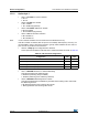
Table 95. LVD threshold configuration
Configuration LVD1 LVD0
LVD Off 11
Highest Voltage Threshold (∼4.1V) 1 0
Medium Voltage Threshold (∼3.5V) 0 1
Lowest Voltage Threshold (∼2.8V) 0 0