
Datasheet


DocID8349 Rev 7 149/170
ST7LITE20F2 ST7LITE25F2 ST7LITE29F2 Electrical characteristics
169
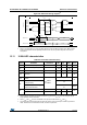
Figure 90. ADC accuracy characteristics with amplifier disabled
• E
T
=Total Unadjusted Error: maximum deviation between the actual and the ideal
transfer curves.
• E
O
=Offset Error: deviation between the first actual transition and the first ideal one.
• E
G
=Gain Error: deviation between the last ideal transition and the last actual one.
• E
D
=Differential Linearity Error: maximum deviation between actual steps and the ideal
one.
• E
L
=Integral Linearity Error: maximum deviation between any actual transition and the
end point correlation line.
Figure 91. ADC accuracy characteristics with amplifier enabled
Note: When the AMPSEL bit in the ADCDRL register is set, it is mandatory that f
ADC
be less than
or equal to 2 MHz (if f
CPU
=8MHz, then SPEED=0, SLOW=1).
• E
T
=Total Unadjusted Error: maximum deviation between the actual and the ideal
transfer curves.
• E
O
=Offset Error: deviation between the first actual transition and the first ideal one.
• E
G
=Gain Error: deviation between the last ideal transition and the last actual one.
• E
D
=Differential Linearity Error: maximum deviation between actual steps and the ideal
one.
• E
L
=Integral Linearity Error: maximum deviation between any actual transition and the
end point correlation line.
E
O
E
G
1LSB
IDEAL
1LSB
IDEAL
V
DD
V
SS
–
1024
--------------------------------=
V
in
(LSB
IDEAL
)
(1) Example of an actual
transfer curve
(2) The ideal transfer curve
(3) End point correlation line
1023
1022
1021
5
4
3
2
1
0
7
6
1234567
1021 1022 1023 1024
(1)
(2)
E
T
E
D
E
L
(3)
V
DD
V
SS
Digital result ADCDR
E
O
E
G
1LSB
IDEAL
1LSB
IDEAL
V
DD
V
SS
–
1024
--------------------------------=
V
in
(LSB
IDEAL
)
(1) Example of an actual
transfer curve
(2) The ideal transfer curve
(3) End point correlation line
Digital Result ADCDR
704
108
0
1234567
701 702 703 704
(1)
(2)
E
T
E
D
E
L
(3)
V
SS
430mV62.5mV
V
in
(OPAMP)