
Datasheet


DocID8349 Rev 7 133/170
ST7LITE20F2 ST7LITE25F2 ST7LITE29F2 Electrical characteristics
169
Figure 66. Typical application with a crystal or ceramic resonator
13.6 Memory characteristics
T
A
= -40°C to 85°C, unless otherwise specified.
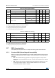
Table 72. Resonator performances
Supplier
f
CrOSC
[MHz]
Typical ceramic resonators
(1)
CL1
(2)
[pF]
CL2
(2)
[pF]
Rd
[Ω]
Supply
voltage
range [V]
Temperature
range [°C]
Type
(3)
Reference
Murata
2 SMD CSTCC2M00G56-R0 (47) (47) 0
2.4V to 5.5V
-40 to 85
4
SMD CSTCR4M00G53-R0 (15) (15) 0
LEAD CSTLS4M00G53-B0 (15) (15) 0
8
SMD CSTCE8M00G52-R0 (10) (10) 0
LEAD CSTLS8M00G53-B0 (15) (15) 0
16
SMD CSTCE16M0V51-R0 (5) (5) 0 3.3V to 5.5V
LEAD CSTLS16M0X53-B0 (15) (15) 0 4.5V to 5.5V
LEAD CSALS16M0X55-B0 7 7 1.5k 3.8V to 5.5V
1. Resonator characteristics given by the ceramic resonator manufacturer. For more information on these resonators,
please consult www.murata.com
2. () means load capacitor built in resonator.
3. SMD = -R0: Plastic tape package (∅=180mm).
LEAD = -B0: Bulk
OSC2
OSC1
f
OSC
C
L1
C
L2
i
2
RESONATOR
WHEN RESONATOR WITH
INTEGRATED CAPACITORS
R
d
ST7LITE2
Table 73. RAM and hardware registers
Symbol Parameter Conditions Min Typ Max Unit
V
RM
Data retention mode
(1)
HALT mode (or RESET) 1.6 −−V
1. Minimum V
DD
supply voltage without losing data stored in RAM (in HALT mode or under RESET) or in hardware registers
(only in HALT mode). Guaranteed by construction, not tested in production.
Table 74. Flash program memory
Symbol Parameter Conditions Min Typ Max Unit
V
DD
Operating voltage for Flash write/erase − 2.4 − 5.5 V