
Datasheet


Electrical characteristics ST7LITE20F2 ST7LITE25F2 ST7LITE29F2
132/170 DocID8349 Rev 7
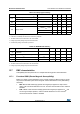
Table 70. Resonator characteristics
Symbol Parameter Conditions Min Typ Max Unit
f
CrOSC
Crystal Oscillator Frequency
(1)
1. When PLL is used, please refer to the Section 13.3.4: Internal RC oscillator and PLL and Section 7:
Supply, reset and clock management (f
CrOSC
min. is 8 Mhz with PLL).
− 2 − 16 MHz
C
L1
C
L2
Recommended load capacitance
versus equivalent serial
resistance of the crystal or
ceramic resonator (R
S
)
−
See Table 72:
Resonator
performances
pF
Table 71: Resonator performances
Supplier
f
CrOSC
[MHz]
Typical ceramic
resonators
(1)
1. Resonator characteristics given by the ceramic resonator manufacturer. For more information on these
resonators, please consult www.murata.com
CL1
(2)
[pF]
2. () means load capacitor built in resonator.
CL2
(2)
[pF]
Rd
[Ω]
Supply
voltage
range [V]
Temperature
range [°C]
Type
(3)
3. SMD = -R0: Plastic tape package (∅=180mm).
LEAD = -B0: Bulk
Reference
Murata
2 SMD CSTCC2M00G56-R0 (47) (47) 0
2.4V to 5.5V
-40 to 85
4
SMD CSTCR4M00G53-R0 (15) (15) 0
LEAD CSTLS4M00G53-B0 (15) (15) 0
8
SMD CSTCE8M00G52-R0 (10) (10) 0
LEAD CSTLS8M00G53-B0 (15) (15) 0
16
SMD CSTCE16M0V51-R0 (5) (5) 0 3.3V to 5.5V
LEAD CSTLS16M0X53-B0 (15) (15) 0 4.5V to 5.5V
LEAD CSALS16M0X55-B0 7 7 1.5k 3.8V to 5.5V