WorldDSLTM Exchange Office Management Unit EMU-830 User Manual Document Number: LTPE-UM-3159-02
REVISION HISTORY The Revision History provides a summary of any changes in this manual. Please make sure you are using the latest revision of this manual. September 25, 2006 Revision Release Date Revisions Made 01 September 30, 2004 Initial release. 02 September 25, 2006 Technical update for L4A/L6A. This manual is available online at ADC’s website (www.adc.com/documentationlibrary/) or you can order copies of the manual by contacting your sales representative.
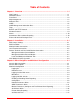
Table of Contents Chapter 1: Overview ....................................................................................................... 1-1 New Features ........................................................................................................................... 1-1 Standard Features .................................................................................................................... 1-1 Front Panel ..........................................................................
Table of Contents September 25, 2006 Change Password ............................................................................................................ 3-18 Set Shelf ID ...................................................................................................................... 3-19 Terminal Settings .............................................................................................................. 3-20 Set to Factory Defaults ................................................
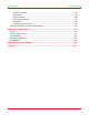
List of Figures Figure 1-1. Figure 1-2. Figure 1-3. Figure 1-4. Figure 1-5. Figure 1-6. EMU-830 Front Panel ....................................................................................... 1-2 Local Management of a Single Shelf Using RS-232/Telnet ............................. 1-4 Remote Management of Multiple Shelves at Two Sites Using Multishelf TAO 1-4 Multishelf TAO Network Screen ....................................................................... 1-5 Multishelf TAO Main Menu Screen ........
List of Figures September 25, 2006 Figure 3-21.Xmodem Transfer Message ........................................................................... 3-26 Figure 3-22.Local Line Unit Uploading Message ............................................................... 3-26 Figure 3-23.Upload EMU Menu Item ................................................................................. 3-28 Figure 3-24.Upload to Local EMU Dialog Box ...................................................................
List of Tables Table 1-1. EMU-830 List 4A and 6A Front Panel Components ........................................... 1-2 Table 1-2. WorldDSL Traps .................................................................................................. 1-8 Table 3-1. Console Menu Navigation Keys .......................................................................... 3-1 Table 3-2. Logon, Network, and Main Menu Screen Selections .......................................... 3-2 Table 3-3.
List of Tables viii September 25, 2006 LTPE-UM-3159-02
ABOUT THIS MANUAL INTRODUCTION This manual contains information on the ADC® WorldDSL™ EMU-830 (hereafter referred to as the “EMU-830”). An Exchange Office Management Unit (EMU) is installed in a WorldDSL Exchange Office Management Shelf (EMS). The EMU provides alarm, fault, configuration, and performance management of HDSL and G.SHDSL circuits deployed from a WorldDSL shelf.
About This Manual September 25, 2006 Reader Alert Meaning Alerts you to possible equipment damage from electrostatic discharge ATTENTION CAUTION WARNING DANGER Alerts you to possible data loss, service-affecting procedures, or other similar type problems Alerts you that failure to take or avoid a specific action might result in hardware damage or loss of service Alerts you that failure to take or avoid a specific action might result in personal harm EU COMPLIANCE This product has been CE marked in
Chapter 1 OVERVIEW The EMU-830 provides management for HDSL and G.SHDSL circuits using either of the following methods: • One or more shelves of HDSL or G.SHDSL circuits can be managed by connecting a management terminal (or PC with terminal emulation software) to the EMU-830 of one shelf. The management terminal (or PC) can be connected to the EMU-830 either directly (or through modems over a dial-up network).
Chapter 1: Overview September 25, 2006 FRONT PANEL Figure 1-1 and Table 1-1 identify and describe the front-panel components of the EMU-830 Lists 4A and 6A. POWER FAIL System status LEDs EXT COMM CRITICAL MAJOR ALM Alarm LEDs MINOR ACO Alarm cut-off LED and switch Reset switch RESET V.24 (RS-232) console port V.24 EMU-830 Figure 1-1. EMU-830 Front Panel Table 1-1.
September 25, 2006 Name Chapter 1: Overview Mode Function Reset switch Resets the EMU-830 hardware. V.24 (RS-232) console port Provides access to EMU console menus either by local terminal connected to console port via serial cable or by remote terminal connected to console port via modems. Also supports autonomous dial-out reporting of alarms to management station. a. It is normal for the Fail LED to illuminate briefly when power is applied to the EMU-830.
Chapter 1: Overview September 25, 2006 WorldDSL Shelf DSL Lines Exchange Switch GSM Base Station NTU/STU-R Video Conference NTU/STU-R To EMU 10Base-T port PC running Telnet Client PBX To EMU Console port from PC serial port VT100 dumb terminal or PC with terminal emulation software Figure 1-2.
September 25, 2006 Chapter 1: Overview Figure 1-4. Multishelf TAO Network Screen Figure 1-5. Multishelf TAO Main Menu Screen A multishelf network is created by connecting the local area network (LAN) to the 10BASE-T Ethernet connector available on a shelf. Each shelf must have an EMU-830 management unit installed. A VT100 terminal (or PC) is connected either locally or remotely (through modems), or through Telnet access to the console port of one EMU in the network.
Chapter 1: Overview September 25, 2006 In a remotely managed configuration, an external modem must be connected to the EMU-830 front panel V.24 (RS-232) console port. If enabled, alarm conditions cause ASCII messages to be transmitted autonomously over the dial-up network. These messages can be displayed on a monitor or sent directly to a printer. This provides the network operator immediate notification of problems.
September 25, 2006 Chapter 1: Overview Network Management Station Unix workstation or PC running SNMP Management Station software/StarGazer Ethernet LAN Ethernet Network PSTN Modem SNMP via LAN SNMP via SLIP Site #2 Site #1 Ethernet LAN Site #3 Site #3 Ethernet LAN Modem RS-232/485 SLIP Port WorldDSL Shelf RS-232/485 SLIP Port WorldDSL Shelf WorldDSL Shelf WorldDSL Shelf Modem WorldDSL Shelf WorldDSL Shelf NTU/STU-R Managed DSL link WorldDSL Shelf Figure 1-6.
Chapter 1: Overview September 25, 2006 IMPORTANT ! These MIB files must be used with the management unit software release. • RFC 1213 MIB II. The Internet-standard MIB for network management of TCP/IP-based internets. It defines objects common to all devices that support SNMP. This includes objects related to generic configuration such as the device's name (sysName), objects related to the transport protocols (IP, TCP, ICMP, etc.
September 25, 2006 Chapter 1: Overview Traps Power supply failure Definition Enterprise trap that indicates the failure of a -48 V shelf power supply input. Multiple DSL loops down Enterprise trap used to indicate when the programmable threshold of the number of downed DSL loops in the shelf has been exceeded. System configuration change Enterprise trap that signals when a change has occurred in the physical configuration of the system, such as the insertion or removal of LTUs/STU-Cs.
Chapter 1: Overview September 25, 2006 ALARMS The EMU-830 constantly monitors each of the DSL cards for alarm conditions. When so configured, the EMU-830 provides autonomous dial-out reporting of alarms to remote management stations and printers (see “Autonomous Dial-out Alarm Reporting” on page 1-10). The EMU-830 List 6A monitors the external 2 MHz clock supplied to the shelf (see “External Shelf Clock Backup Circuit” on page 1-11).
September 25, 2006 Chapter 1: Overview EXTERNAL SHELF CLOCK BACKUP CIRCUIT The EMU-830 List 6A includes a backup circuit for the 2.048 MHz external shelf clock. This circuit will continue to provide a 2.048 MHz clock to the DSL cards in the event the 2.048 MHz external shelf clock is lost. The software reports the status of this circuit and allows the user to set the severity of the alarm generated when the clock is lost. A block diagram of the clock backup circuit is shown in Figure 1-8 on page 1-11.
Chapter 1: Overview 1-12 September 25, 2006 LTPE-UM-3159-02
Chapter 2 INSTALLATION This section describes the procedures for installing the EMU-830. Note: Each shelf in a Multishelf TAO network must have an EMU-830 management unit installed. Inserting and removing the EMU-830 from a shelf will not affect the operation of the DSL cards installed in the shelf. An EMU-830 failure will not affect the operation of the DSL cards installed in the shelf. EMU JUMPER SETTINGS EMU-830s are jumper configurable for an RS-232 or RS-485 SLIP port interface.
Chapter 2: Installation September 25, 2006 EMU INSTALLATION Install the EMU-830 in an EMS-830 as follows: Step 1 Action Use a flat-blade screwdriver to loosen the two screws holding the EMU slot faceplate (Slot 17) in place, then remove the slot faceplate (Figure 2-2). EMS-830 shelf EMU slot faceplate Figure 2-2.
September 25, 2006 Chapter 2: Installation Step Action 2 Align the EMU-830 card with the card guides at the top and bottom edges of Slot 17, then push the card in until the EMU-830 front panel is flush with the front of the shelf (Figure 2-3). The connector positions in slots 1 through 16 prevent the EMU-830 from being installed in the wrong slot. EMS-830 shelf EMU-830 Figure 2-3.
Chapter 2: Installation September 25, 2006 MULTISHELF CABLE CONNECTIONS Note: Multishelf networks cannot be connected through a router because the local shelf uses UDPbroadcast messages as a mechanism to automatically discover other shelves in the network, and routers generally filter these broadcasts. A multishelf network is limited to 32 shelves.
September 25, 2006 Chapter 2: Installation LOCAL TERMINAL CONNECTIONS The console port of the EMU-830 in the local shelf can be connected directly to a VT100 terminal (or PC). Once connected, you can use the terminal (or PC) to access the EMU-830 console menus. The console menus allow you to configure each EMU and DSL circuit in a multishelf network, monitor and test system performance, and display the inventory of installed DSL units.
Chapter 2: Installation September 25, 2006 Step 1 Action Connect a serial cable from the DB-9 or DB-25 serial port on the maintenance terminal or PC to the V.24 (RS-232) console port on the EMU front panel (Figure 2-6). Maintenance terminal or PC with terminal emulation program EMU-830 DB-9 or DB-25 serial port RS-232 cable V.24 console port Figure 2-6.
September 25, 2006 Chapter 2: Installation REMOTE TERMINAL AND LOCAL SHELF MODEM CONNECTIONS Remote management of one or more Multishelf TAO sites over a telephone network requires the connection of a modem to the remote management station and to the EMU residing in the local shelf of each site. Once connected, the remote management station can access the console menus of one or more multishelf networks to configure, monitor, and test their EMU and DSL circuits.
Chapter 2: Installation September 25, 2006 Step Action 1 Connect the shelf modem to the PC and verify that it is in working condition as described in the preceding section, “Management Station External Modem.” 2 Use a communications program to send the following initialization string to the modem: AT&F This string resets the modem to its original factory configuration and clears any previous programming that can conflict with the communication between the modem and the EMU.
September 25, 2006 Chapter 2: Installation Step 4 Action Connect a serial cable (with pinouts as specified below) to the EMU console port connector (DB-9F) of the local shelf. IMPORTANT ! The modem-to-EMU serial cable must have the connector pinouts shown in Figure 2-7 to function correctly. RD (Receive Data) TD (Transmit Data) GND DCD (Data Carrier Ready) DSR (Data Set Ready) Figure 2-7.
Chapter 2: Installation Step September 25, 2006 Action 6 Configure the EMU for SNMP operation over SLIP (see “Configure SNMP Operation Over SLIP” on page 3-10). 7 Configure the EMU modem parameters for remote alarm reporting. Refer to “Modem Parameters (Configure and Test Dial-out Alarm Reporting)” on page 3-14 for details. SD (Send Data) RD (Receive Data) RTS (Request to Send) CTS (Clear to Send) DSR (Data Set Ready) GND DTR (Data Terminal Ready) Figure 2-8.
Chapter 3 MENU NAVIGATION AND MULTISHELF CONFIGURATION CONSOLE MENU NAVIGATION Single keystrokes are used to make menu selections and, where applicable, select available options. Use the keys described in Table 3-1 to navigate through the console menus, menu items, and screens: Table 3-1. Console Menu Navigation Keys Press this Key To Perform this Function Alphanumeric keys Select and execute an underlined or highlighted menu item. Also used for typing in text fields.
Chapter 3: Provisioning September 25, 2006 Table 3-2. Logon, Network, and Main Menu Screen Selections Screens and Selections Displays and Functions Logon Password screen Displays date and time and Password text box (Figure 3-1 on page 3-3.
September 25, 2006 Chapter 3: Provisioning MULTISHELF CONFIGURATION The sections that follow contain instructions on how to access the EMU-830 console menus to configure and monitor each EMU and DSL circuit in a multishelf network. Note: Multishelf TAO has two main screens, the Network screen and the Main menu screen.
Chapter 3: Provisioning September 25, 2006 Network Screen Note: The shelf with the > symbol (for example, >Shelf #28 in Figure 3-2) is the local shelf connected to the management station PC. Other shelves without the > symbol are remote shelves connected to the local shelf through an Ethernet subnet. The Network screen (Figure 3-2) includes the Login command, Upload menu, and Quit command.
September 25, 2006 Chapter 3: Provisioning Figure 3-3. Main Menu Screen Shelf Alarms The state of shelf and DSL alarms is continuously updated in the Main Menu screen. There are two possible shelf alarms, both of which can be classified as Minor, Major, Critical, or Disabled: • Power Supply Failure (POWER A or POWER B). This is a loss of -48 Vdc power at input A or B on the rear of the shelf. • DSL alarm (HDSL LINKS). This alarm indicates when a programmable number of DSL loops in the shelf are down.
Chapter 3: Provisioning September 25, 2006 Table 3-3. DSL Line Unit Status Conditions State Indicator Description Normal – The circuit has no active alarms. This can be because one or more of the circuit's alarms are disabled from being reported at the DSL card. Not Occupied / No unit is installed in the slot, or the unit is not recognized. Alarms Disabled D Alarm reporting has been disabled for this circuit at the EMU-830. This can be changed using selection 2 from the Main menu.
September 25, 2006 Chapter 3: Provisioning 9 AIS Alarm Indication signal on any G.703 interface HDSL G.SHDSL 10 LFA Loss of Frame alarm on any G.703 interface HDSL G.SHDSL 11 RAI Remote Alarm Indication on any G.703 interface HDSL G.SHDSL Logging into DSL Circuits To log into the console menu for an DSL card: Step Action 1 In the Main menu screen (Figure 3-3 on page 3-5), type the number 1 in the ENTER SELECTION field and press ENTER. The Enter line unit number field is displayed.
Chapter 3: Provisioning September 25, 2006 Enabling or Disabling Alarm Reporting To enable or disable alarm reporting for DSL circuits: Step Action 1 In the Main menu screen (Figure 3-3 on page 3-5), type the number 1 in the ENTER SELECTION field and press ENTER. The Enter line unit number field displays the current line unit selection and Enable or Disable setting. 2 Enter a line unit number, then use the Ç arrow key to select the current Enable or Disable setting.
September 25, 2006 Chapter 3: Provisioning Figure 3-5. Network Parameters Menu Note: The network parameters for each EMU must be configured individually. Once configured, each shelf reports its status and alarms to the local shelf (the shelf with its EMU connected to the VT100 or PC, either directly or by modem). The Ethernet Address parameter is read-only and cannot be changed by the user. When changes are made to the network parameters, the EMU console will prompt to reset to apply the changes.
Chapter 3: Provisioning September 25, 2006 Configure SNMP Operation Over SLIP To configure the EMU-830 for basic SNMP operation over SLIP: Step Action 1 In the Network Parameters menu (Figure 3-5 on page 3-9), enter the Local SLIP IP Address (see Table 3-5 on page 3-10). 2 Enter the Local SLIP Subnet Mask. 3 Use the SPACEBAR to select the SLIP Port Baud Rate. 4 Press ENTER to confirm all network settings. 5 Follow the EMU console prompt to reset the EMU.
September 25, 2006 Chapter 3: Provisioning Option Function Local SLIP Subnet Mask Allows the EMU-830 to determine if a host (TFTP server, SNMP management station, or trap receiver) is on the same local subnet. If it is, the EMU-830 can communicate directly with the host; if it is not, messages must be sent through a default router. 0.0.0.0 is the default setting. SLIP Port Baud Rate Select the SLIP Port baud rate by toggling to the desired rate (maximum 19200 bps).
Chapter 3: Provisioning September 25, 2006 Configure SNMP Community Strings The community string parameters are required to read and write SNMP objects. In the SNMP Parameters menu (Figure 3-6 on page 3-11), configure the Read-only and Read-Write Community String parameters in accordance with Table 3-6. Configure SNMP Trap Receivers The SNMP Parameters menu allows you to configure up to three SNMP trap receivers (management stations) to which all EMU-830 trap messages will be sent.
September 25, 2006 Chapter 3: Provisioning Option Function Trap 1 Community String Enter a community string. It must match the SNMP Comm Name string for traps. SNMP uses the community string for set and get requests. Trap 1 Validation Select the trap status by toggling between Valid (the default) or Invalid. Valid enables the trap, invalid disables it. Trap 2 IP Address Enter the IP address to which the trap is sent. 0.0.0.0 is the default setting.
Chapter 3: Provisioning September 25, 2006 Modem Parameters (Configure and Test Dial-out Alarm Reporting) In the Config menu, press M to display the Modem Parameters menu (Figure 3-7). This menu is used to configure the EMUs modem parameters for autonomous dial-out reporting of alarms to a remote management station or printer. Figure 3-7. Modem Parameters Menu Note: Connect and configure the shelf modem as instructed in “Remote Terminal and Local Shelf Modem Connections” on page 2-7.
September 25, 2006 Step 8 Chapter 3: Provisioning Action Test the EMU’s dial-out alarm reporting as follows: a. Configure the shelf alarms as instructed on page 3-16. b. If necessary, select the Remote Alarm Reporting menu item and press ENTER to change the setting from disable (Dis) to enable (Ena). See Figure 3-8. IMPORTANT ! The following steps require that you momentarily disconnect an DSL Tip or Ring lead and then a G.703 interface cable to test remote alarm reporting.
Chapter 3: Provisioning September 25, 2006 Figure 3-9. LOS*, PFO* and LOSW* Alarm Reporting Screen Shelf Alarms Menu In the Config menu, press H to display the Shelf Alarms menu (Figure 3-10). This menu allows you to enable, disable, and set the severity of the loss of shelf power, HDSL/G.SHDSL lines down, and loss of external clock alarm. The Config menu also allows you to configure how each of the alarm relays respond to an ACO (Alarm Cut-Off).
September 25, 2006 Chapter 3: Provisioning To configure the shelf alarms: Step Action 1 Navigate the menu using the Ç and È arrow keys on the keyboard. 2 In the Loss of power on one 48V supply field, use the SPACEBAR to select DIS (disabled), MIN (minimum), MAJ (major), or CRT (critical). 3 In the HDSL alarm if 3 lines down field, use the SPACEBAR to select DIS (disabled), MIN (minimum), MAJ (major), or CRT (critical).
Chapter 3: Provisioning September 25, 2006 To set the date and time: Step Action 1 Use the Ç and È arrow keys to select the DD/MM/YYYY and HH:MM:SS fields. Enter the current date and time in the respective fields. 2 Press ENTER to confirm settings and return to the top of the Config menu. Figure 3-12. Set Date/Time Dialog Box Change Password In the Config menu, press P to display the Change Password dialog box (Figure 3-13 on page 3-19). This dialog box is used to select or change your password.
September 25, 2006 Chapter 3: Provisioning Figure 3-13. Change Password Dialog Box Set Shelf ID In the Config menu, press I to display the Set Shelf ID dialog box (Figure 3-14 on page 3-19). This dialog box allows you to enter the shelf ID for each management unit. You can use the letters A through Z (case sensitive), numbers 0 through 9, spaces, and any symbol. Figure 3-14.
Chapter 3: Provisioning September 25, 2006 To set the shelf ID: Step Action 1 In the Enter Shelf ID field, type the Shelf ID (32 characters maximum) and press ENTER. 2 Press any key to return to the top of the Config menu. 3 Reset the EMU as instructed on page 3-22. Terminal Settings In the Config menu, press T to display the Terminal Settings menu (Figure 3-15). This menu is used to specify a terminal setting that displays the best horizontal and vertical lines on your monitor. Figure 3-15.
September 25, 2006 Chapter 3: Provisioning To specify a terminal setting, do one of the following: Step Action 1 If you are not using a Windows terminal, select a menu item with the best horizontal line, then press ENTER. For example, "_ _ _ _ _" versus "________", where "________" is the best. 2 If you are using a Windows terminal, select the Windows Terminal menu item, then press ENTER.
Chapter 3: Provisioning September 25, 2006 Reset EMU In the Config menu, press R to display the "reset EMU" warning prompt (Figure 3-17). Figure 3-17. Reset EMU Warning Prompt IMPORTANT ! If you reset the EMU-830, all alarm reporting information is lost. Note: Resetting the EMU will log you off from the EMU console menu and requires that you log on again on to regain access.
September 25, 2006 Chapter 3: Provisioning Figure 3-18. Inventory Information Screen Table 3-7. Data in Inventory Information Screen Field Description Product Type Displays the EMU model number. List Number Displays the EMU list number, which identifies the version of the unit. Hardware Revision Displays the EMU hardware revision number Serial Number Displays the unique serial number of the EMU for inventory and service tracking. Manufacture Date Displays the date the EMU was manufactured.
Chapter 3: Provisioning September 25, 2006 MANAGING FIRMWARE THROUGH THE UPLOAD MENU The Upload menu provides the mechanism to upload image files to local or remote line units or EMUs. Upload to a Local or Remote Line Unit To upad to a local or remote line unit: Step Action 1 If viewing the Main menu screen (Figure 3-3 on page 3-5), press ESC and type Q to return to the Network screen (Figure 3-2 on page 3-4).
September 25, 2006 Chapter 3: Provisioning Figure 3-19. Upload Line Unit Menu Item Figure 3-20. Upload to Line Unit Dialog Box Table 3-8.
Chapter 3: Provisioning September 25, 2006 Figure 3-21. Xmodem Transfer Message Figure 3-22.
September 25, 2006 Chapter 3: Provisioning Upload Local EMU To upload to the local EMU: Note: If using the Xmodem protocol to upload the local EMU directly from your management station, copy the firmware file to your management station hard disk before proceeding. This greatly reduces the time required for the upload process. Step Action 1 In the Network screen (Figure 3-2 on page 3-4), select the local shelf. That is, the shelf with the ">" symbol. For example, >Shelf # 28. 2 Type the letter U.
Chapter 3: Provisioning September 25, 2006 Figure 3-23. Upload EMU Menu Item Figure 3-24.
September 25, 2006 Chapter 3: Provisioning Figure 3-25. TFTP Upload EMU Prompt Figure 3-26.
Chapter 3: Provisioning September 25, 2006 Figure 3-27. Boot Loader Prompt Upload Remote EMU After uploading the local EMU, its firmware image can be uploaded to the remote EMUs (the use of files is not required). To upload to a remote EMU: Step Action 1 In the Network screen (Figure 3-2 on page 3-4), select a remote shelf. That is, a shelf without the ">" symbol. For example, Shelf # 27. 2 Type the letter U. The Upload menu is displayed (Figure 3-19 on page 3-25).
September 25, 2006 Chapter 3: Provisioning Figure 3-29.
Chapter 3: Provisioning 3-32 September 25, 2006 LTPE-UM-3159-02
Appendix A SPECIFICATIONS ALARMS Relays 6 form C relays: critical visual, critical audible, major visual, major audible, minor visual, minor audible. Maximum switching power 30 W Maximum switching current 1A Surge voltage withstand 1500 V Shelf alarms Power input failure, programmable number of HDSL loops in the shelf are down, loss of external clock (EMU-830 List 6A only) LEDs Critical, Major, Minor alarm POWER REQUIREMENTS Consumption 7.
Appendix A: Specifications A-2 September 25, 2006 LTPE-UM-3159-02
Appendix B PRODUCT SUPPORT ADC Customer Service Group provides expert pre-sales support and training for all of its products. Technical support is available 24 hours a day, 7 days a week by contacting the ADC Technical Assistance Center. Sales Assistance: 800.366.3891 Quotation Proposals, Ordering and Delivery General, and Product Information Systems Integration: 800.366.
Appendix B: Product Support B-2 September 25, 2006 LTPE-UM-3159-02
GLOSSARY A AIS – Alarm Indication Signal ALM – Alarm ANSI – American National Standards Institute AWG – American Wire Gage B BER – Bit Error Rate C C – Centigrade COM – Communication CRC – Cyclic Redundancy Check CTS – Clear To Send D D15F – D-type 15-pin Female Connector D25F – D-type 25-pin Female Connector D9F – D-type 9-pin Female Connector dB – Decibel DCE – Data Communications Equipment Det – Detector dnl – Download DS0 – Digital Service, Level 0 (64 kbps) DSR – Data Set Ready DTE – Data Terminal E
Glossary September 25, 2006 K kbps – kilobytes per second km – kilometers L LED – Light Emitting Diode LL – Local Loopback LDC – Loss of Data Port (Nx64k) Clock LEC – Loss of External Clock LOC – Loss of Clock LOSW – Loss of Sync Word LPBK – Loopback LTU – Line Termination Unit M M34F – M-type 34-pin Female Connector MAR – Margin Mbps – Megabits per second MHz – Megahertz mm – millimeter N NC – Normally Closed NO – Normally Open NTU – Network Termination Unit NVRAM – Non-volatile Random Access Memory N
September 25, 2006 Glossary T TM – Test Mode TT – Terminal Timing U UAS – Unavailable Seconds UTU – Universal Termination Unit V V – Volts Vdc – Volts direct current VT100 – A terminal-emulation system W W – Watts LTPE-UM-3159-02 GL-3
Glossary GL-4 September 25, 2006 LTPE-UM-3159-02
Certification and Warranty FCC Class A Compliance This equipment has been tested and found to comply with the limits for a Class A digital device, pursuant to Part 15 of the FCC Rules. These limits are designed to provide reasonable protection against harmful interference when the equipment is operated in a commercial environment.
World Headquarters ADC Telecommunications, Inc. PO Box 1101 Minneapolis, MN 55440-1101 USA For Technical Assistance Tel: 800.366.