ML-96 Service Manual American Dryer Corporation 88 Currant Road Fall River, MA 02720-4781 Telephone: (508) 678-9000 / Fax: (508) 678-9447 e-mail: techsupport@amdry.com 080699DMG/tcosta ADC Part No.
Retain This Manual In A Safe Place For Future Reference American Dryer Corporation products embody advanced concepts in engineering, design, and safety. If this product is properly maintained, it will provide many years of safe, efficient, and trouble-free operation. ONLY qualified technicians should service this equipment. OBSERVE ALL SAFETY PRECAUTIONS displayed on the equipment or specified in the installation/operator's manual included with the dryer.
IMPORTANT YOU MUST DISCONNECT and LOCKOUT THE ELECTRIC SUPPLY and THE GAS SUPPLY SUPPLY BEFORE ANY COVERS or GUARDS ARE REMOVED FROM THE MACHINE TO ALLOW ACCESS FOR CLEANING, ADJUSTING, INSTALLATION, or TESTING OF ANY EQUIPMENT per OSHA (Occupational Safety and Health Administration) STANDARDS. Caution: Label all wires prior to disconnection when servicing controls. Wiring errors can cause improper operation.
WARNING The dryer must never be operated with any of the back guards, outer tops, or service panels removed. PERSONAL INJURY or FIRE COULD RESULT. WARNING DRYER MUST NEVER BE OPERATED WITHOUT THE LINT FILTER/SCREEN IN PLACE, EVEN IF AN EXTERNAL LINT COLLECTION SYSTEM IS USED. IMPORTANT PLEASE OBSERVE ALL SAFETY PRECAUTIONS displayed on the equipment and/or specified in the installation and operator's manual included with the dryer.
Table of Contents SECTION I IMPORTANT INFORMATION ............................................................................... 3 A. Safety Precautions ..................................................................................................................... 3 SECTION II ROUTINE MAINTENANCE .................................................................................... 5 A. Cleaning .........................................................................................................
SECTION V SERVICING .............................................................................................................. 15 A. B. C. D. E. F. G. H. I. J. K. L. M. N. O. P. Q. Computer Controls ................................................................................................................. 15 Ignition Controls ......................................................................................................................
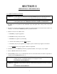
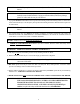
SECTION I IMPORTANT INFORMATION A. SAFETY PRECAUTIONS WARNING: For your safety, the information in this manual must be followed to minimize the risk of fire or explosion or to prevent property damage, personal injury, or loss of life. WARNING: The dryer must never be operated with any of the back guards, outer tops, or service panels removed. PERSONAL INJURY or FIRE COULD RESULT. 1. DO NOT store or use gasoline or other flammable vapors and liquids in the vicinity of this or any other appliance. 2.
WARNING: DO NOT dry mop heads. Contamination by wax or flammable solvents will create a fire hazard. WARNING: DO NOT use heat for drying articles that contain plastic, foam, sponge rubber, or similarly textured rubber materials. Drying in a heated tumbler (basket) may damage plastics or rubber and also may be a fire hazard. 7. A program should be established for the inspection and cleaning of lint in the heating unit area, exhaust duct work, and inside the dryer.
SECTION II ROUTINE MAINTENANCE A. CLEANING A program and schedule should be established for periodic inspection, cleaning, and removal of lint from various areas of the dryer, as well as throughout the duct work system. The frequency of cleaning can best be determined from experience at each location. Maximum operating efficiency is dependent upon proper air circulation. The accumulation of lint can restrict this airflow.
EVERY 6 MONTHS Inspect and remove lint accumulation in customer furnished exhaust duct work system and from dryers internal exhaust ducting. WARNING: THE ACCUMULATION OF LINT IN THE EXHAUST DUCT WORK CAN CREATE A POTENTIAL FIRE HAZARD. WARNING: DO NOT OBSTRUCT THE FLOW OF COMBUSTION and VENTILATION AIR. CHECK CUSTOMER FURNISHED BACK DRAFT DAMPER IN EXHAUST DUCT WORK. INSPECT and REMOVE ANY LINT ACCUMULATION WHICH CAN CAUSE DAMPER TO BIND or STICK.
SECTION III INSTALLATION REQUIREMENTS Installation should be performed by competent technicians in accordance with local and state codes. In the absence of these codes, the installation must conform to applicable AMERICAN NATIONAL STANDARDS: National Fuel Gas Code ANSI.Z223.1-LATEST EDITION or National Electrical Code ANSI/NFPA No. 70LATEST EDITION, or in Canada, the installation must conform to applicable Canadian Standards: CAN/CGAB149.1-M91 (Natural Gas) or CAN/CGA-B149.2-M91 (L.P.
IMPORTANT: Failure to comply with these codes or ordinances and the requirements stipulated in this manual can result in personal injury or component failure. The dryer installation must meet the American National Standard, National Fuel Gas Code ANSI Z223.1LATEST EDITION, or in Canada, the Canadian Electrical Codes Parts 1 & 2 CSA C22.1-1990 or LATEST EDITION (for Electrical Connections) as well as, local codes and ordinances, and must be done by a qualified technician.
NOTE: Water column pressure requirements (measured at the pressure tap on the gas valve body): Natural Gas - 3.5 inches water column (W.C.) - 8.7 mb. L.P. Gas - 10.5 inches water column (W.C.) - 26.1 mb. 6. If computer program changes are required, refer to the Phase 6 OPL Operators Manual (ADC Part No. 113022) for details. 7. The dryer should be operated through one complete cycle to assure that no further adjustments are necessary and that ALL components are functioning properly. 8.
SECTION IV DESCRIPTION OF PARTS A. COMPUTER PANEL (MICROPROCESSOR) Lifting the control door will reveal the control panel assembly. Opening the control panel will allow access to the major components which include the computer board and keypad (touchpad). The keypad (touchpad) inputs to the computer what temperature and program has been selected. The computer controls the entire operation of the machine. It accepts inputs and gives outputs throughout the machine. B.
C. HSI (HOT SURFACE IGNITION) MODULE (Gas Models Only) The HSI (Hot Surface Ignition) system consists of a microprocessor based control module, along with a hot surface ignitor probe and a flame probe assembly. The hot surface ignitor is a silicon carbide ignitor that upon application of 24 VAC will glow bright orange for the inter-purge time period.
F. DRIVE SHAFT ASSEMBLY (Viewing from the front of the dryer.) Behind front panel on the left side of the dryer, you can view the drive shaft assembly which consists of a 9-inch (22.86 cm) drive pulley, two (2) 6-inch (15.24 cm) wheels, one (1) taper lock bearings, and one (1) 1inch (2.54 cm) pillow block bearings. G. IDLER SHAFT ASSEMBLY (Viewing from the front of the dryer.
I. MAIN DOOR SWITCH The main door switch is mounted to the front panel behind the main door. When the main door opens, the switch will also open, preventing the dryer from operating. The main door switch is a safety device and should never be disabled. J. SAIL SWITCH (Gas Models Only) The sail switch is located on the front of the burner box. A sail switch consists of a round damper plate on a lever arm which is in contact with an electric switch.
L. MANUAL RESET THERMOSTAT This is located inside the dryer in the lint compartment above the lint screen. This thermostat senses the heated air after it passes through the tumbler (basket). If the air temperature gets too hot, the thermostat will shut off the burner. The dryer will not run until the air temperature cools down. At this time, the manual reset thermostat must be reset manually or the 24 VAC burner circuit will never be completed.
SECTION V SERVICING INTRODUCTION ALL electrical and mechanical service or repairs should be made with the electrical power to the dryer disconnected (power off). WARNING: PERSONAL INJURY COULD RESULT. The information provided in this section should not be misconstrued as a device for use by an untrained person making repairs. Service work should be performed by competent technicians in accordance with local, state, and federal codes.
4. Remove the two (2) screws securing the computer to the computer panel. Remove the computer by pulling the other two (2) corners off the clinch studs. 5. Install new computer by reversing this procedure. Keyboard (Touchpad) Label Assembly Replacement 1. Discontinue electrical power to the dryer. 2. Unplug keyboard (touchpad) ribbon from rear of the computer. 3. Slowly peel off and remove keyboard (touchpad) label assembly from control panel. 4.
B. IGNITION CONTROLS Hot Surface Ignition Module Replacement (refer to burner illustration on page 11) 1. Discontinue electrical power to the dryer. 2. Disconnect wire from S1 and GND on the HSI (Hot Surface Ignition) module. 3. Disassemble ignitor from burner by removing the one (1) self tapping screw. 4. Reverse procedure for installation of new ignitor. NOTE: Before reestablishing electrical power to the dryer visually check the following (refer to illustration above). 5.
NOTE: DO NOT WRAP THE HOT SURFACE IGNITOR WIRES AND THE FLAME ELECTRODE WIRE TOGETHER. IMPROPER OPERATION MAY RESULT. THEY MAY RUN ALONGSIDE EACH OTHER. 5. Reestablish procedure for installation of new ignitor. Gas Valve Replacement (Refer to burner illustration on page 11) 1. Discontinue electrical power to the dryer. 2. Close shut-off valves in gas supply line. 3. Disconnect gas valve wiring. NOTE: Identify location of each wire for correct reinstallation. 4.
To Test and Adjust Gas (Water Column) Pressure There are two (2) types of devices commonly used to measure column pressure. They are spring and mechanicaltype gauges and manometers. The spring and mechanical-type gauge is not recommended, because it is easily damaged and not always accurate. A manometer is simply a glass or transparent plastic tube with a scale in inches. When filled with water and pressure applied, the water in the tube rises showing the exact water column pressure.
3. Reverse the procedure for reinstalling valve assembly to the dryer. WARNING: Test ALL connections for leaks by brushing on a soapy water solution. WARNING: NEVER TEST FOR LEAKS WITH A FLAME!!! NOTE: There is no regulator provided in an L.P. dryer. The column pressure must be regulated at the source (L.P. tank) or an external regulator must be added to each dryer. Burner Tubes Replacement 1. Refer to Replace Gas Valve and follow Step #1 through Step #6. 2.
C. MANUAL RESET BURNER HI-LIMIT (330º F [166º C]) THERMOSTAT REPLACEMENT (Gas Models Only) 1. This thermostat is an important safety device as an added protection against failure of the airflow (sail switch) to open in the event of motor failure or reduced airflow conditions. IMPORTANT: UNDER NO CIRCUMSTANCES should heat circuit safety devices ever be disabled. NOTE: Models manufactured as of 1998 are equipped with a manual reset hi-limit thermostat. 1. Discontinue electrical power to the dryer. 2.
D. SAIL SWITCH ASSEMBLY (Gas Models Only) The sail switch is a heat circuit safety device which controls the burner circuit only. When the dryer is operating and there is proper airflow, the sail switch damper pulls in and closes the sail switch. Providing ALL the other heat-related circuits are functioning properly, ignition should now be established. If an improper airflow occurs, the sail switch damper will release, and the circuit will open. Sail Switch Replacement 1.
IMPORTANT: UNDER NO CIRCUMSTANCES should the door switch be disabled. Main Door Assembly Replacement 1. Open main door. 2. Holding the door upward remove the two (2) screws from the top hinge block. 3. Lift the door up to remove. 4. Reverse this procedure for reinstalling new main door assembly. To Install New Main Door Glass 1. Remove main door assembly from dryer (follow main door removal procedure). 2. Lay main door on flat surface with the back of the door facing down. 3.
Front Panel Replacement 1. Discontinue electrical power to the dryer. 2. Remove bottom lint drawer assembly. 3. Remove the screws securing the front panel to the dryer. 4. Disconnect the two (2) door switch wires located behind the front panel. 5. Remove the front panel. IMPORTANT: When pulling the front panel off, the door switch harness in the upper right hand corner must be unplugged. NOTE: The main door assembly can be removed to make the panel removal easier.
F. DRIVE SHAFT PULLEY REPLACEMENT 1. Discontinue electrical power to the dryer. 2. Remove front panel from dryer (Follow front panel replacement directions on page 24.) 3. Loosen V-belts. Rotate pulley and roll V-belts out of grooves. 4. Remove set screw from the 9 (22.86 cm) pulley. 5. Remove pulley and key. NOTE: A gear puller may be required to remove pulley. 6. Reverse this procedure for replacement. NOTE: Pulley must be aligned for proper operation. Drive Motor Pulley Replacement 1.
5. Loosen V-belts. Rotate pulley and V-belts out of the groove. 6. Block the tumbler (basket) assembly in position. 7. Mark the position of pillow block bearing then remove the bolts from the pillow block bearings. 8. Remove the drive shaft assembly through the front of the machine. 9. Remove the set screw from the 9 (22.86 cm) pulley. 10. Remove the pulley and key. NOTE: A gear pulley may be required to remove the pulley. 11. Remove cap screws from bushing. 12.
3. Remove the ten (10) 1/4-20 x 1/4 socket button head screws from the perforated basket side. 4. Remove the wrapper assembly. 5. Block the tumbler (basket) assembly in position. 6. Mark the position of the pillow block bearings. Then remove the bolts from the pillow block bearing. 7. Remove the idler shaft assembly through the front of the machine. 8. Remove the cap screws from bushing. 9. Insert cap screws in the tapped removal holes and tighten evenly until bushing becomes loose on shaft. 10.
3. Depress the tabs on the rotational sensor harness plug and pull apart. 4. Remove the retaining ring from the tumbler shaft. 5. Remove the four (4) bolts, lock washers and flat washers securing the flange bearing to the dryer cabinet. 6. Loosen the set screws from the flange bearing. 7. Remove the flange bearing from the tumbler shaft. 8. To replace new flange bearing reverse Step #2 through Step #8. 9. Reestablish electrical power to the dryer. K.
L. IDLER SHAFT PILLOW BLOCK BEARING REPLACEMENT 1. Refer to tumbler wheel replacement on idler assembly page 26. 2. Complete Step #1 through Step #11. 3. Remove both set screws from each pillow block bearing. 4. Remove pillow block bearing from shaft. 5. Reverse this procedure for replacement. NOTE: Once the shaft assembly has been installed into dryer. Return pillow block bearings to the marked position and tighten set screws. 6. Refer to basket assembly section page 27 for shaft and basket alignment. M.
8. Retighten motor mount bolts and jam nuts. 9. Assemble front panel lint door assemblies back to dryer. 10. Reestablish electrical power to the dryer. Drive Motor V-Belts Replacement 1. Discontinue electrical power to the dryer. 2. Remove the belt guard cover from the rear of the dryer. 3. Loosen tension on V-belt so that it can easily be rolled off pulley. This can be done by loosening the four (4) bolts holding the motor to the side of the dryer, as well as the adjustment bolt on top. 4. Replace V-belt.
P. MOTORIZED IMPELLOR (BLOWER) REPLACEMENT 1. Discontinue electrical power to the dryer. 2. Remove lint draw. 3. Remove the perforated panel inside the tumbler (basket). 4. Remove the bolts securing the inlet cone. 5. Remove the inlet cone. 6. Remove the bolts securing the motor plate to the dryer cabinet. 7. Remove the motorized impellor along with the motor plate. NOTE: The motorized impellor assembly will not be able to be removed due to the wiring harness still connected. 8.
SECTION VI TROUBLESHOOTING IMPORTANT: YOU MUST DISCONNECT and LOCKOUT THE ELECTRIC SUPPLY and THE GAS SUPPLY BEFORE ANY COVERS or GUARDS ARE REMOVED FROM THE MACHINE TO ALLOW ACCESS FOR CLEANING, ADJUSTING, INSTALLATION, or TESTING OF ANY EQUIPMENT per OSHA (Occupational Safety and Health Administration) STANDARDS. The information provided will help isolate the most probable component(s) associated with the difficulty described.
C. Dryer will not start, but computer L.E.D. (light emitting diode) indicators are on... 1. Failed contactors. 2. Failed arc suppressor (A.S.) board. 3. Failed microprocessor controller (computer). 4. Failed motors. D. Drive motor runs, burner is on, but tumbler (basket) will not turn... 1. Broken, damaged or loose V-belt. 2. Belts contaminated (oil, grease, etc.). 3. Loose or broken pulley. E. Dryer operates but is taking too long to dry... 1. Improperly programmed microprocessor controller (computer).
F. Thermal overload for drive motor is tripping... 1. Either an exceptionally low or high voltage supply. 2. Motor bearing failure. 3. Motor vents are blocked with lint. 4. Failed motor. 5. Failed overload. 6. Out of balance impellor (fan). 7. Insufficient make-up air. G. Overload for impellor (fan) motor is tripping... 1. Either an exceptionally low or high voltage supply. 2. Motor bearing failure. 3. Motor vents are blocked with lint. 4. Failed motor. 5. Failed overload. 6. Insufficient make-up air. H.
I. L.E.D. (light emitting diode) display reads Temp Sensor Failure Check Temp Sensor Fuse. Dryer Sensor Circuit Failure... 1. Check 1/8-amp fuse on microprocessor controller (computer). 2. Faulty microprocessor temperature sensor probe. 3. Open circuit in either one of two (2) wires leading from the sensor probe to the computer... 4. a. Connection at sensor bracket assembly connector. b. Connection at computer harness connector. Faulty microprocessor controller (computer). J. Dryer does not start.
SECTION VII PHASE 6 OPL SYSTEM DIAGNOSTICS IMPORTANT: YOU MUST DISCONNECT and LOCKOUT THE ELECTRIC SUPPLY and THE GAS SUPPLY BEFORE ANY COVERS or GUARDS ARE REMOVED FROM THE MACHINE TO ALLOW ACCESS FOR CLEANING, ADJUSTING, INSTALLATION, or TESTING OF ANY EQUIPMENT per OSHA (Occupational Safety and Health Administration) STANDARDS. ALL major circuits, including door, microprocessor temperature sensor, heat and motor circuits are monitored.
6. bURNER CONTROL FAIL- This routine monitors the ignition controls gas valve output response. If the valve output signal is not present from the ignition control within the valve time limits the Phase 6 microprocessor controller (computer) determines the ignition control has failed. If this occurs when the cycle is active the machine will display bURNER CONTROL FAIL. If the tumbler temperature is above 100º F (38º C) the machine will continue to display bURNER CONTROL FAIL.
11. ROTATE SENSOR FAIL- Indicates a rotational sensor circuit failure meaning that there is a fault somewhere in the tumbler (basket) rotating circuit, or the Phase 6 OPL microprocessor controller (computer) program related to this circuit (program location 2) is set incorrectly. In the active mode it should be (ROTATE SENSOR ACTIVE), if the dryer is not equipped with the optional rotational sensor it should be set in the nonactive mode (No ROTATE SENSOR).
4. L.E.D. DISPLAY INDICATOR NUMBER 4 a. On Indicator: 1) This indicator dot is on whenever a cycle is in progress. Additionally, when the Anti-Wrinkle program is active, the indicator dot will be on whenever the Phase 6 OPL microprocessor controller (computer) is in the Guard On Time program. 5. L.E.D. DISPLAY INDICATOR NUMBER 5 a. Air Jet Circuit - OPTIONAL 1) This indicator dot is on at the end of the dryer cycle for approximately 60 seconds. C.
1. FAN (BLOWER) Output L.E.D. (light emitting diode) Indicator a. If the dryer is started and the blower motor is not operating, yet the Phase 6 OPL microprocessor controller (computer) display fan indicator dot and power supply input L.E.D. (light emitting diode) are on, but the fan output L.E.D. is off, then the fault is the Phase 6 OPL microprocessor controller (computer) itself. 1) If the motor is not operating. The fan indicator dot and output L.E.D.
6. FUSE (MAIN FUSE) Input L.E.D. (light emitting diode) Indicator a. Should be on ALL the time (even if the dryer is not running). If the L.E.D. (light emitting diode) is not on; then the display will read CHECK MAIN FUSE. If the main fuse is good then the fault is on the Phase 6 microprocessor controller (computer). 7. LINT (LINT DOOR) Input L.E.D. (light emitting diode) Indicator a. Should be on ALL the time (unless the lint door is opened then the LINT L.E.D.
12. FLAME (bURNER CONTROL FAIL) Input L.E.D. (light emitting diode) Indicator a. This routine monitors the ignition controls gas valve output response. If the valve output signal is not present from the ignition control within the valve time limits the microprocessor determines the ignition control has failed. If this occurs when the cycle is active the FLAME output L.E.D. (light emitting diode) indicator will go out and the display will read bURNER CONTROL FAIL.
D. L.E.D. CODES 1.
2.
E. COMPUTER LOGIC and WIRING DIAGRAM 1. Operator enters desired selections. 2. Information entered is sent to the microprocessor via the keyboard (touchpad). 3. The input information is sorted, processed and executed by the microcomputer chip. 4. The microcomputer output signal activates the contactors and HSI (Hot Surface Ignition) module which control machine functions. NOTE: When contacting ADC with electrical questions, please have on hand the correct wiring diagram number for your particular machine.
46
1. No Display Condition a. Check position of EMERGENCY STOP (E-Stop) to verify it is in operating position (pull or twist for operating position). b. Check fuse one or two and if either are blown, replace. c. Take voltage reading across the microprocessor (J7) 9-pin connector pins 1 and 2. If no voltage is present at pins 1 and 2, double check the secondary (24 VAC) side of transformer at the blower motor contactor number 13 to ground if no voltage is present check primary voltage to transformer. d.
If there is voltage, replace the coil or the complete contactor. If there is no voltage, check for voltage across the two BS3 terminals on the arc suppressor (A.S.) board. If there is voltage across the two BS3 terminals and no voltage across the coil of the reversing contactor (A1 and A2), the problem is faulty wires or terminations between BS1 and the contactor coil. d. If there is no voltage between the two BS3 terminals on the arc suppressor (A.S.
c. If no voltage is present at J7 9-pin connector no. 4 to ground, but voltage is present at no. 3 to ground. The problem is a faulty switch, wires or termination between J7 to J8 and J8 to the lint switch no. 20 and 21. d. If no voltage is present at J7 9-pin connector no. 3 to ground, then voltage should not be present at no. 5 to ground. Replace the board. 6. Main Door Condition NOTE: Make sure main door and lint door are closed. Also, if checking either switch, the plunger must be depressed. a.
IMPORTANT MANUAL RESET HI-LIMIT INSTRUCTIONS FOR PHASE 6 MODELS This dryer was manufactured with a manual reset burner hi-limit and tumbler/lint chamber hi-limit thermostat which is monitored by the Phase 6 computer. If either manual reset thermostat is open prior to start of the drying cycle, the dryer will start momentarily and then shut down, the Phase 6 computer will display an error code with an audio indication.
SECTION VIII TECHNICAL INFORMATION The following section contains various technical information important to the service person in servicing and maintaining the dryer. A. MOTOR PLATE (HIGH and LOW VOLTAGE) The motor plate is located on the side of the drive motor (refer to illustration) and contains a graphical representation of the motor wiring for both low and high voltage ratings. Removing the cap reveals the wiring to the motor.
B. DATA LABEL Contacting American Dryer Corporation (ADC) When contacting ADC, certain information is required to ensure proper service and parts information. This information is on the data label, located on the top right corner of the dryer, viewed from the rear (refer to illustration). When contacting ADC, please have the model number and serial number readily accessible. Information on the Data Label a.
C. HOW TO USE A MANOMETER 1. With dryer in nonoperating mode, remove plug on the gas valve pressure tap. 2. Attach plastic tubing to pressure tap. Fitting is supplied with manometer (see illustration). 3. Attach manometer to dryer using magnet. NOTE: Place manometer in a position so that readings can be taken at eye level. 4. Fill manometer with water, as shown in illustration to the zero level. 5. Start dryer. With burner on, take a reading. a. Read water level at the inner tube.
D.
ADC 450406 1- 02/09/00-25