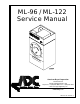
ML-96 / ML-122 Service Manual American Dryer Corporation 88 Currant Road Fall River MA 02720-4781 USA Telephone: +1 (508) 678-9000 / Fax: +1 (508) 678-9447 e-mail: techsupport@amdry.com www.amdry.com ADC Part No.
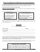
Retain This Manual In A Safe Place For Future Reference American Dryer Corporation products embody advanced concepts in engineering, design, and safety. If this product is properly maintained, it will provide many years of safe, efficient, and trouble free operation. ONLY qualified technicians should service this equipment. OBSERVE ALL SAFETY PRECAUTIONS displayed on the equipment or specified in the installation manual included with the dryer.
IMPORTANT You must disconnect and lockout the electric supply and the gas supply or the steam supply before any covers or guards are removed from the machine to allow access for cleaning, adjusting, installation, or testing of any equipment per OSHA standards. “Caution: Label all wires prior to disconnection when servicing controls. Wiring errors can cause improper operation.” Table of Contents _______ Important Information ............................................ 4 Safety Precautions .................
Important Information _______________ Safety Precautions WARNING: For your safety, the information in this manual must be followed to minimize the risk of fire or explosion or to prevent property damage, personal injury, or loss of life. ! The dryer must never be operated with any of the back guards, outer tops, or service panels removed. Personal injury or fire could result. Do not store or use gasoline or other flammable vapors and liquids in the vicinity of this or any other appliance.
Lubrication NOTE: Frequency can best be determined at each location. The drive shaft bearings and idler shaft bearings should be lubricated every 3 months. Use a #3 grease or equivalent. Lubrication is necessary. Daily (Beginning) of each work shift. Clean lint from the drawer and screen. Inspect lint screen and replace if torn. Weekly Clean lint accumulation from lint chamber, thermostat, and microprocessor temperature sensor (sensor bracket) area.
! CAUTION: Improperly sized or installed exhaust ductwork can create a potential fire hazard. Electrical and Gas Requirements It is your responsibility to have all electrical connections made by a properly licensed and competent electrician to assure the electrical installation is adequate and conforms with local and state regulations or codes.
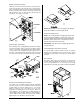
Reversing Relay Panel Lifting the control door will reveal the reversing relay box. Located on the back of the relay box is the reversing relay panel. Included on this panel is a 4-position terminal block, blower overload, blower contactor, reversing contactor, 24 VAC transformer, fuse or circuit breaker, ground lug, and possibly an arc suppressor board. NOTE: With the dryer off or no air supply to the damper piston, the damper is in the cool down mode.
Drive Shaft Assembly Main Door Switch (Viewing from the front of the dryer) The main door switch is mounted to the front panel behind the main door. When the main door opens, the switch will also open, preventing the dryer from operating. The main door switch is a safety device and should never be disabled. Behind front panel on the right side of the dryer, you can view the drive shaft assembly, which consists of a 9-inch (22.86 cm) drive pulley, two 6-inch (15.24 cm) wheels, and two 1-inch (2.
Temperature Sensor Bracket Servicing _____________________________ This is located inside the dryer in the lint compartment above the lint screen. This bracket consists of 2 devices. One is a temperature sensor probe and the other is a high limit thermostat, which is set at 225º F (107º C). Introduction All electrical and mechanical service or repairs should be made with the electrical power to the dryer disconnected (power off). ! WARNING: Personal injury could result.
Connect keypad ribbon to the computer. The flame-probe, ignitor probe, and ground rod are all on the same line of axis. Reestablish electrical power to the dryer. There should be a 1/8” gap (+/- 1/32) between the ignitor probe and ground rod. Microprocessor Temperature Sensor Probe Replacement Do not wrap the red high voltage wire and flame-probe wire together. (Improper operation may result.) They may run along side each other. Discontinue electrical power to the dryer.
! WARNING: Test all connections for leaks by brushing on a soapy water solution. NEVER TEST FOR LEAKS WITH A FLAME!!! Ignition Module Replacement Discontinue electrical power to the dryer. Remove the wires connected to the terminal strip at the bottom of the module. (Mark correct location of each wire to aid in replacement on new module). To Convert Natural Gas to L.P. Gas Remove the 2 pal nuts securing the module to the mounting bracket.
Tumbler Hi-Limit Thermostat (225º F [107º C]) Replacement Sail Switch Adjustment Disconnect electrical power to the dryer. Open lint door. Locate sensor bracket assembly, remove the 2 nuts securing bracket assembly to the tumbler wrapper. Remove bracket assembly by slightly sliding bracket toward the rear of the dryer and to the left. Disconnect sensor bracket harness connector and remove bracket assembly from dryer. Disconnect the 2 “orange” wires from the thermostat.
Steam Coil Replacement ! Discontinue electrical service to the dryer. Disconnect compressed air supply from the dryer. Shut off all steam supply lines and steam return valves that feed the steam coil. WARNING: The 1/2” plug must be closed before attempting to apply any steam pressure. Slowly open the return line then slowly open the supply line. Wait a sufficient amount of time until all of the steam lines and the steam coil is cool.
Main Door Assembly Replacement IMPORTANT: When pulling the front panel off, the door switch harness in the upper right hand corner must be unplugged. Open main door. Holding the door upward remove the 2 screws from the top hinge block. Lift the door up to remove. Reverse this procedure for reinstalling new main door assembly. NOTE: The main door assembly can be removed to make the panel removal easier. Refer to “Replace Main Door Assembly” directions.
Tumbler Wheel Replacement on Drive Assembly Discontinue electrical power to the dryer. Remove front panel from dryer. (Follow front panel replacement directions on page 14.) Remove the 10 1/4-20 x 1/4” socket button head screws from the perforated basket side. Remove wrapper assembly. Loosen V-belt. Rotate pulley and V-belt out of the groove. Block the tumbler assembly in position. Remove the setscrew from the 9-inch (22.86 cm) pulley. Remove the pulley and key.
Check the basket drive belt for proper tension. Adjust if necessary. Replace the wrapper panels. Replace the perforated tumbler panel. 1-15/16 (5 cm) Flange Bearing Replacement Disconnect electrical power to the dryer. Remove the 4 bolts securing the bearing cap located in the rear of the dryer. And remove. Depress the tabs on the rotational sensor harness plug and pull apart. Remove the retaining ring from the tumbler shaft.
Refer to basket assembly section page 15 for shaft and basket alignment. V-Belt Adjustment (Motor to Drive Axle) Discontinue electrical power to the dryer. Remove the belt guard cover from the rear of the dryer. Loosen the 4 bolts holding the drive motor mount to the side of the dryer. Loosen the jam nuts on the adjustment screw on the top of the motor mount. Turn the adjustment screw to lower the motor mount (to tighten the belts) or raise the motor mount (to loosen the belts.
Lint Door Switch Replacement Discontinue electrical power to the dryer. No L.E.D. display on microprocessor controller (computer)... Remove the lint door panel. (For the ML-122.) Open circuit breaker switch or blown fuse. Remove the front panel. (For the ML-96.) Tripped blower motor overload. Disconnect both 4-pin connectors at the rear of the lint switch cover. Faulty wiring connection. Remove the 2 screws holding the lint switch cover on. “Emergency Stop” (E-Stop) button is depressed.
Phase 6 OPL System Diagnostics ___ Overload for impellor (fan) motor is tripping... IMPORTANT: You must disconnect and lockout the electric supply and the gas supply or the steam supply before any covers or guards are removed from the machine to allow access for cleaning, adjusting, installation, or testing of any equipment per OSHA standards. Either an exceptionally low or high voltage supply. Motor bearing failure. Motor vents are blocked with lint. Failed motor. Failed overload.
bURNER CONTROL FAIL – This routine monitors the ignition control’s gas valve output response. If the valve output signal is not present from the ignition control within the valve time limits the Phase 6 microprocessor controller (computer) determines the ignition control has failed. If this occurs when the cycle is active the machine will display “bURNER CONTROL FAIL.” If the tumbler temperature is above 100º F (38º C) the machine will continue to display “bURNER CONTROL FAIL.
L.E.D. Display Indicator Number 4 On Indicator: This indicator dot is on whenever a cycle is in progress. Additionally, when the Anti-Wrinkle program is active, the indicator dot will be on whenever the Phase 6 OPL microprocessor controller (computer) is in the Guard On Time program. L.E.D. Display Indicator Number 5 Air Jet Circuit – OPTIONAL: This indicator dot is on at the end of the dryer cycle for approximately 60-seconds. Phase 6 OPL Microprocessor Controller (Computer) Relay Output L.E.D.
If the dryer is active (running) and the lint door is opened the “LINT” L.E.D. indicator will go out and the display will read “LINT dOOR.” The dryer will stop until the lint drawer has been closed, at which time the L.E.D. display will read “PRESS START.” At this time, to resume the drying cycle press “ENTER/START” key. “MAIN” (MAIN DOOR) Input L.E.D. Indicator Should be on all the time (unless the lint door is open or the main door is opened then the “MAIN” L.E.D. indicator will go out).
EE PROM FAULT ### – Error in memory location. The ### indicates the location of the fault. Data Label ___________________________ Contacting American Dryer Corporation Input/Output Board L.E.D. Indicators Inputs ESTOP – (RED L.E.D.): This L.E.D. will indicate the status of the E-STOP. If the E-STOP has been pressed, then the L.E.D. is on. GAS_V – (RED L.E.D.): This L.E.D. will indicate the status of the gas valve. If the gas valve is open (ON), then the L.E.D. is on. BRHL – (RED L.E.D.): This L.E.D.
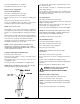
How to Use a Manometer With dryer in nonoperating mode, remove plug on the gas valve pressure tap. Notes ________________________________________ Attach plastic tubing to pressure tap. Fitting is supplied with manometer (refer to illustration). ______________________________________________ Attach manometer to dryer using magnet. ______________________________________________ NOTE: Place manometer in a position so that readings can be taken at eye level.
Notes _____________________________________________________________________________________________ ___________________________________________________________________________________________________ ___________________________________________________________________________________________________ ___________________________________________________________________________________________________ ___________________________________________________________________________________________________ ____________
ADC Part No.