
Installation manual

42
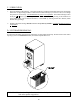
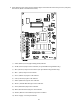
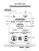
d. Verify that the motor(s) heat, and door indicator lights on the back side of the microprocessor (computer)
board are lit. (Refer to the illustration below.)
1) FAN (Blower) L.E.D. (light emitting diode) indicator
2) FOR (Forward) output L.E.D. indicator (for optional Reversing Models Only)
3) Rev (Reverse) output L.E.D. indicator (for optional Reversing Models Only)
4) HT 1 (Heat) output L.E.D. indicator
5) Fuse (Main Fuse) input L.E.D. indicator
6) Lint (Lint Door) input L.E.D. indicator
7) Main (Main Door) input L.E.D. indicator
8) Drum (Tumbler Hi-Limit) input L.E.D. indicator
9) Sail (Sail Switch) input L.E.D. indicator
10) Burn (Burner Hi-Limit) input L.E.D. indicator
11) Flame (Burner Control Failure) input L.E.D. indicator
12) Power Supply L.E.D. Input Indicator