
User guide


General Overview
EV10AQ190x-DK - User Guide 1-3
1067BX–BDC–12/11
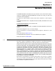
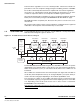
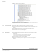
1.3 Demo Kit Figure 1-2 provides an overview of system architecture.
Figure 1-2. EV10AQ190x-DK Demo Kit System Architecture (when Connected with a VIRTEX6 Evaluation Kit)
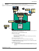
The complete system is built with the e2v demo kit and an FPGA development kit.
e2v Demo kit contains the following items :
Quad 10-bit Demo kit with EV10AQ190CTPY ADC
Cables & Power Supply
– Universal 12V power Adapter & Cables
– USB Cables to communicate with a PC (control of ADC settings and settings
for data acquisition)
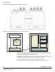
4 analog inputs with SMA connectors
1 clock input with SMA connector (if external clock input is programming)
2 SAMTEC MC-HPC-8.5L connectors HPC (High Pin Count) compatible with VITA57
standard for ADC LVDS digital outputs
CD ROM with GUI Software
Note: The ML605 VIRTEX 6 Evaluation kit with XC6VVLX240T-1FFG1156 FPGA is not sup-
plied within the e2v kit and should be purchased separately from Xilinx or its authorised
distributors.
RF generator
PC
GUI
control,
acquisition
& analysis
12V supply
adapter
FPGA
(VIRTEX 6)
VITA57 interface
e2v
QUAD 10-bit
4 channels
12V supply
adapter
I/O USB control
A
B
C D
DN
CLK