
User guide

Software Tools
EV10AQ190x-DK - User Guide 4-19
1067BX–BDC–12/11
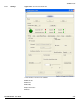
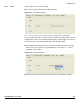
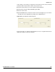
4.5.2 TEST In this window, the test mode is available:
A ramp test is generated within each ADC and output
Figure 4-34. Test Ramp Test Mode
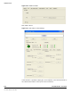
Note: this mode allows synchronizing the 4 channels of ADC with the FPGA RESET.
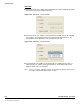
The synchronizing procedure can be initiated by checking the Disable button and then
the Apply button : Then check the ADC and Ramp button and then Apply. Then retrun to
normal operation by checking the Disable button and clicking on Apply.
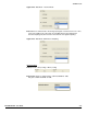
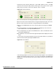
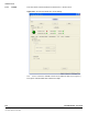
A flashing bit is generated with one bit at 1 within each ADC and output is following
with ten bit at 0 (1 FF pattern every ten 00 patterns) or after every 11 or 15 zeros
depending on the selection.
Figure 4-35. Flashing Test Mode
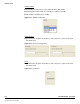
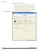
FPGA Test (for testing communication between Demo kit and FPGA) : ramp test