
Installation manual

14 American Dryer Corp. 113363-6
IMPORTANT: DO NOT use screens, louvers, or caps on the outside opening of the exhaust
ductwork.
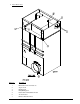
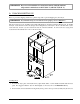
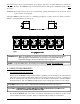
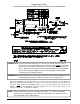
2. Single Dryer Venting
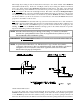
Where possible, it is suggested to provide a separate exhaust duct for each dryer. The exhaust duct should
be laid out in such a way that the ductwork travels as directly as possible to the outdoors with as few turns
as possible. It is suggested that the use of 90° turns in the ducting be avoided; use 30° and/or 45° angles
instead. The shape of the exhaust ductwork is not critical as long as the minimum cross section area is
provided.
IMPORTANT: The minimum duct size for a gas unit is 16-inches (40.64 cm) for a round duct and
14-1/4” x 14-1/4” (36.2 cm x 36.2 cm) for a square duct. THE DUCT SIZE
MUST NOT BE REDUCED ANYWHERE DOWNSTREAM OF THE
DRYER.
IMPORTANT: Exhaust back pressure measured by a manometer at each basket (tumbler) exhaust
duct area must be no less than 0 and must not exceed 0.3 inches (0.74 mb) of water
column (W.C.).
It is suggested that the ductwork from each dryer not exceed 20 feet (6.09 meters) with no more than two
(2) elbows (excluding dryer connections). If the ductwork exceeds 20 feet (6.09 meters) or has numerous
elbows, the cross-sectional area of the ductwork must be increased in proportion to the length and number
of elbows in it. In calculating duct size, the cross-sectional area of a square or rectangular duct must be
increased twenty percent (20%) for each additional 20 feet (6.09 meters). The diameter of a round
exhaust duct should be increased ten percent (10%) for each additional 15 feet (4.57 meters). Each 90º
elbow is equivalent to an additional 40 feet (12.19 meters), and each 45º elbow is equivalent to an additional
20 feet (6.09 meters).
Single Dryer Venting