ML-122 Installation Manual Phase 7 / Non-Coin WARNING: For your safety the information in this manual must be followed to minimize the risk of fire or explosion or to prevent property damage, personal injury or death. AVERTISSEMENT: Assurez-vous de bien suivre les instructions données dans cette notice pour réduire au minimum le risque d’incendie ou d’explosion ou pour éviter tout dommage matériel, toute blessure ou la mort.
Retain This Manual In A Safe Place For Future Reference American Dryer Corporation products embody advanced concepts in engineering, design, and safety. If this product is properly maintained, it will provide many years of safe, efficient, and trouble-free operation. ONLY qualified technicians should service this equipment. OBSERVE ALL SAFETY PRECAUTIONS displayed on the equipment or specified in the installation manual included with the dryer.
IMPORTANT YOU MUST DISCONNECT AND LOCKOUT THE ELECTRIC SUPPLYAND THE GAS SUPPLY OR THE STEAM SUPPLY BEFORE ANY COVERS OR GUARDS ARE REMOVED FROM THE MACHINE TO ALLOW ACCESS FOR CLEANING, ADJUSTING, INSTALLATION, OR TESTING OF ANY EQUIPMENT PER OSHA (Occupational Safety and Health Administration) STANDARDS. “Caution: Label all wires prior to disconnection when servicing controls. Wiring errors can cause improper operation.
WARNING The dryer must never be operated with any of the back guards, outer tops, or service panels removed. PERSONAL INJURY OR FIRE COULD RESULT. WARNING DRYER MUST NEVER BE OPERATED WITHOUT THE LINT FILTER/SCREEN IN PLACE, EVEN IF AN EXTERNAL LINT COLLECTION SYSTEM IS USED. IMPORTANT PLEASE OBSERVE ALL SAFETY PRECAUTIONS displayed on the equipment and/or specified in the installation manual included with the dryer.
Table of Contents SECTION I SAFETY PRECAUTIONS ........................................................................................................ 2 SECTION II SPECIFICATIONS/COMPONENT IDENTIFICATION ....................................................... 4 A. Specifications .......................................................................................................................................... 4 B. Component Identification ..............................................................
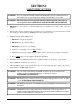
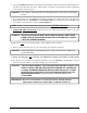
SECTION I SAFETY PRECAUTIONS WARNING: For your safety, the information in this manual must be followed to minimize the risk of fire or explosion or to prevent property damage, personal injury, or loss of life. WARNING: The dryer must never be operated with any of the back guards, outer tops, or service panels removed. PERSONAL INJURY OR FIRE COULD RESULT. 1. DO NOT store or use gasoline or other flammable vapors and liquids in the vicinity of this or any other appliance. 2.
. A program should be established for the inspection and cleaning of lint in the burner area, exhaust ductwork, and area around the back of the dryer. The frequency of inspection and cleaning can best be determined from experience at each location. WARNING: The collection of lint in the burner area and exhaust ductwork can create a potential fire hazard. 8. For personal safety, the dryer must be electrically grounded in accordance with local codes and/or the National Electrical Code ANSI/NFPA NO.
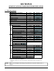
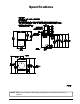
SECTION II SPECIFICATIONS/COMPONENT IDENTIFICATION A. SPECIFICATIONS Steam* Electric Gas* MAXIMUM CAPACITY (DRY WEIGHT) TUMBLER DIAMETER TUMBLER DEPTH TUMBLER VOLUME TUMBLER/DRIVE MOTOR BLOWER/FAN MOTOR DOOR OPENING (DIAMETER) DOOR SILL HEIGHT WATER CONNECTION DRYERS PER 20’/40’ CONTAINER DRYERS PER 48’/53’ TRUCK VOLTAGE AVAILABLE APPROX. NET WEIGHT APPROX.
Specifications NOTE: ADC reserves the right to make changes in specifications at any time without notice or obligation. 113363-6 www.amdry.
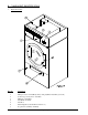
B. COMPONENT IDENTIFICATION 1. Dryer Front View Illus. No. 1 2 3 4 5 6 7 6 Description Microprocessor Control/Keyboard (touch pad) Panel Assembly (controls) Control (top access) Door Assembly Main Door Assembly Lint Panel Assembly Lint Door Wire Diagram (located behind control door) Top Console (module) Assembly American Dryer Corp.
2. Dryer Rear View Illus. No. 1 2 3 4 5 6 7 113363-6 Description Electrical Service Connections Top Console Heating Unit Relay/Wiring Box Data Label and Installation Label Air Connection Exhaust Transition Piece www.amdry.
SECTION III INSTALLATION PROCEDURES Installation should be performed by competent technicians in accordance with local and state codes. In the absence of these codes, the installation must conform to applicable American National Standards: ANSI Z223.1LATEST EDITION (National Fuel Gas Code) or ANSI/NFPA NO. 70-LATEST EDITION (National Electrical Code) or in Canada, the installation must conform to applicable Canadian Standards: CAN/CGA-B149.1-M91 (Natural Gas) or CAN/CGA-B149.2-M91 (Liquid Propane [L.P.
IMPORTANT: Dryer must be installed in a location/environment, which the ambient temperature remains between 40° F (4.44° C) and 130° F (54.44° C). B. UNPACKING/SETTING UP Remove protective shipping material (i.e., plastic wrap and/or optional shipping box) from dryer. IMPORTANT: Dryer must be transported and handled in an upright position at ALL times. The dryer can be moved to its final location while still attached to the skid or with the skid removed.
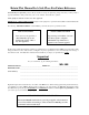
To Remove Top Console (module): a. Disconnect the ground wire (A in the illustration below) located at the rear upper left corner of the dryer. b. Remove the six (6) sets of nuts and washers (B in the illustration below) holding the console (module) to the base. c. Disconnect the white plug connector (C in the illustration below) located on the top of the rear electric service/relay box (provides power to the heat circuit). d. Disconnect air connection from the 3-way micro valve. e.
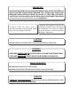
C. DRYER ENCLOSURE REQUIREMENTS Bulkheads and partitions should be made of noncombustible material. NOTE: Allowances must be made for opening the control door. A 38-inches (76.2 cm) for optimum opening of load door. B The maximum thickness of the bulkhead for gas dryers is 4-inches (10.16 cm). For electric and steam dryers the maximum thickness of the bulkhead is 1-inch (2.54 cm) within 3-inches (7.62 cm) from the top of the control door.
It is not necessary to have a separate make-up air opening for each dryer. Common make-up air openings are acceptable. However, they must be set up in such a manner that the make-up air is distributed equally to ALL the dryers. EXAMPLE: For a bank of six (6) dryers, two (2) unrestricted openings measuring 3 feet by 3 feet (0.91 meters by 0.91 meters) are acceptable.
When single dryer venting is used, the ductwork from the dryer to the outside exhaust outlet should not exceed 20 feet (6.09 meters). In the case of multiple (common) dryer venting, the distance from the last dryer to the outside exhaust outlet should not exceed 20 feet (6.09 meters). The shape of the ductwork is not critical as long as the minimum cross-sectional area is provided. It is suggested that the use of 90º turns be avoided; use 30º and/or 45º bends/angles instead.
IMPORTANT: DO NOT use screens, louvers, or caps on the outside opening of the exhaust ductwork. 2. Single Dryer Venting Where possible, it is suggested to provide a separate exhaust duct for each dryer. The exhaust duct should be laid out in such a way that the ductwork travels as directly as possible to the outdoors with as few turns as possible. It is suggested that the use of 90° turns in the ducting be avoided; use 30° and/or 45° angles instead.
IMPORTANT: For extended ductwork runs, the cross section area of the ductwork can only be increased to an extent. Maximum proportional ductwork runs cannot exceed 20 feet (6.09 meters) more than the original limitations of 20 feet (6.09 meters) with two (2) elbows. When the ductwork approaches the maximum limits as noted in this manual, a professional heating, ventilating, and air-conditioning (HVAC) firm should be consulted for proper venting information.
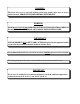
Multiple Dryer Venting 16-Inch (40.64 cm) Diameter Minimum Exhaust Connections at Common Duct IMPORTANT: For extended ductwork runs, the cross section area of the ductwork can only be increased to an extent. Maximum proportional ductwork runs cannot exceed 20 feet (6.09 meters) more than the original limitations of 20 feet (6.09 meters) with two (2) elbows.
F. ELECTRICAL INFORMATION 1. Electrical Requirements It is your responsibility to have ALL electrical connections made by a properly licensed and competent electrician to ensure that the electrical installation is adequate and conforms to local and state regulations or codes. In the absence of such codes, ALL electrical connections, material, and workmanship must conform to the applicable requirements of the National Electrical Code ANSI/NFPA NO.
b. Electric Models ONLY ELECTRICAL SERVICE SPECIFICATIONS (PER DRYER) IMPORTANT: NOTES: A. B. C. 208 VAC AND 240 VAC ARE NOT THE SAME. When ordering, specify exact voltage. When fuses are used they must be dual element, time delay, current limiting, class RK1 or RK5 ONLY. Calculate/determine correct fuse value, by applying either local and/or National Electrical Codes to listed appliance amp draw data. Circuit breakers are thermal-magnetic (industrial) type ONLY.
NOTE: A CIRCUIT SERVICING EACH DRYER MUST BE PROVIDED. 4. Grounding A ground (earth) connection must be provided and installed in accordance with state and local codes. In the absence of these codes, grounding must conform to applicable requirements of the National Electrical Code ANSI/NFPA NO. 70-LATEST EDITION, or in Canada, the installation must conform to applicable Canada Standards: Canadian Electrical Codes Parts 1 & 2 CSA C22.1-1990 or LATEST EDITION.
1. Gas Supply The gas dryer installation must meet the American National Standard...National Fuel Gas Code ANSI Z223.1-LATEST EDITION, or in Canada, the Canadian Installation Codes CAN/CGA-B149.1 M91 (Natural Gas) or CAN/CGA-B149.2-M91 (Liquid Propane [L.P. Gas]) or LATEST EDITION, as well as local codes and ordinances and must be done by a qualified professional. NOTE: Undersized gas piping will result in ignition problems, slow drying, increased use of energy, and can create a safety hazard.
2) Liquid Propane (L.P.) Gas Dryers made for use with L.P. gas have the gas valve’s internal pressure regulator blocked open so that the gas pressure must be regulated upstream of the dryer. The pressure measured at each gas valve pressure tap must be a consistent 10.5 inches (26.1 mb) water column. There is no regulator or regulation provided in an L.P. dryer. The water column pressure must be regulated at the source (L.P. tank) or an external regulator must be added to each dryer.
IMPORTANT: Pipe joint compounds that resist the action of natural gas and liquid propane (L.P.) gas must be used. IMPORTANT: Test ALL connections for leaks by brushing on a soapy water solution (liquid detergent works well). WARNING: NEVER TEST FOR LEAKS WITH A FLAME!!! IMPORTANT: The dryer and its individual shutoff valve must be disconnected from the gas supply piping system during any pressure testing of that system at test pressures in excess of 1/2 psig (3.5 kPa).
H. STEAM INFORMATION It is your responsibility to have ALL plumbing connections made by a qualified professional to ensure that the gas plumbing installation is adequate and conforms to local and state regulations or codes. IMPORTANT: Failure to comply with the requirements stipulated in this manual can result in component failure, which will VOID THE WARRANTY.
c. Flexible hoses or couplings must be used. The dryer vibrates slightly when it runs and this will cause the steam coil connections to crack if they are hard piped to the supply and return mains. d. Shutoff valves for each dryer should be installed in the supply line, return line, and drip trap return line. This will allow the dryer to be isolated from the supply main and the return main if the dryer needs maintenance work. e. Install an inverted bucket steam trap and check valve at least 12-inches (30.
b. Air Connection Air connection to system --- 1/8” F.P.T. c. No air regulator or filtration is provided with the dryer. External regulation/filtration of 80 psi (5.51 bar) must be provided. It is suggested that a regulator/filter gauge arrangement be added to the compressed air line just before the dryer connection. This is necessary to ensure that correct and clean air pressure is achieved. 5.
6. Steam Damper Air Piston (Flow Control) Operation Adjustment Although the steam damper operation was tested and adjusted prior to shipping at 80 psi (5.51 bar), steam damper operation must be checked before the dryer is put into operation. Refer to page 30 for instructions to check steam damper operation. If steam damper adjustment is necessary, locate the flow control valve and make the necessary adjustments as noted below. I.
Installation 1. Requirements The fire suppression system must be supplied with a minimum water pipe size of 1/2” and be provided with 40 psi +/- 20 psi (2.75 bar +/- 1.37 bar) of pressure. For use of optional manual bypass, a second source with the same piping and pressure requirements is required. Flexible 1/2 feeds must be provided to avoid damage to electric water solenoid valve by vibration. IMPORTANT: Flexible supply line/coupling must be used.
Typical water supply: OPTIONAL MANUAL BYPASS Provisions are made in the dryer’s fire suppression system for the installation of an optional manual bypass. Depending on the model dryer, the connections for the manual bypass are made at the “T” or “four way” fitting located in the outlet supply side of the water solenoid valve. The use and connections of this manual bypass are at the option or discretion of the owner.
3. Electrical Requirements No independent external power source or supply connection is necessary. The 24 volt power to operate the fire suppression system is accomplished internally in the dryer (from the dryer controls). WARNING: Electrical power must be provided to the dryer at ALL times. If the main electrical power supply to the dryer is disconnected, the fire suppression system is INOPERATIVE!! J.
K. PREOPERATIONAL TESTS ALL dryers are thoroughly tested and inspected before leaving the factory. However, a preoperational test should be performed before the dryer is publicly used. It is possible that adjustments have changed in transit or due to marginal location (installation) conditions. 1. Turn on electric power to the dryer. 2. Make sure the main door is closed and the lint drawer is securely in place. 3. Refer to the Operating Instructions for starting your particular model dryer. 4.
6. Make a complete operational check of ALL safety-related circuits (i.e., lint drawer switch, and sail switch on gas models). NOTE: To check for proper sail switch operation, open the main door and while holding main door switch plunger in, start the dryer. The dryer should start but the heat circuit should not be activated (on). If the heat (burner) does activate, shut the dryer off and make the necessary adjustments. 7.
NOTE: Press and hold the “UP ARROW” to view the basket (tumbler) temperature at any time. NOTE: The dryer can be stopped at any time by pressing the “STOP/CLEAR” key, at this time the dryer will go into a cycle pause. If the “STOP/CLEAR” key is pressed again at this point, the cycle that was in progress will be cancelled and returned to the “READY” state. NOTE: Press and hold the “DOWN ARROW” to view the basket (tumbler) RPM. 5.
M. COMPRESSED AIR REQUIREMENTS The dryer requires an external supply of compressed air (3.25 cfh at 80 psi [0.09 cmh at 5.51 bar] for gas models and 4.25 cfh at 80 psi [0.12 cmh at 5.51 bar] for steam models). For steam models, compressed air is necessary for the air operated steam damper. On both the steam models as well as the gas models, compressed air is necessary/required for blower air jet operation to clean lint from the impellor/fan (squirrel cage). 1.
N. SHUTDOWN INSTRUCTIONS If the dryer is to be shut down (taken out of service) for a period of time, the following must be performed: 1. Discontinue power to the dryer either at the external disconnect switch or the circuit breaker. 2. Discontinue the heat supply: a. GAS MODELS - discontinue the gas supply. SHUT OFF external gas supply shutoff valve. b. STEAM MODELS - discontinue the steam supply. SHUT OFF external (location furnished) shutoff valve. 34 American Dryer Corp.
SECTION IV SERVICE/PARTS INFORMATION A. SERVICE Service must be performed by a qualified trained technician, service agency, or gas supplier. If service is required, contact the reseller from whom the ADC equipment was purchased. If the reseller cannot be contacted or is unknown, contact the ADC Service Department for a reseller in your area.
SECTION V WARRANTY INFORMATION A. RETURNING WARRANTY CARDS Before any dryer leaves the ADC factory test area, a warranty card is placed on the back side of the main door glass. These warranty cards are intended to serve the customer where we record the individual installation date and warranty information to better serve you should you file a warranty claim. If a warranty card did not come with your dryer, contact the ADC Warranty Department or the ADC Service Department at (508) 678-9000.
2. Each part must be tagged with the following information: a. Model number and serial number of the dryer from which part was removed. b. Nature of failure (be specific). c. Date of dryer installation. d. Date of part failure. e. Specify whether the part(s) being returned is for a replacement, a credit, or a refund. NOTE: If a part is marked for a credit or a refund, the invoice number covering the purchase of the replacement part must be provided.
SECTION VI ROUTINE MAINTENANCE A. CLEANING A program and/or schedule should be established for periodic inspection, cleaning, and removal of lint from various areas of the dryer, as well as throughout the ductwork system. The frequency of cleaning can best be determined from experience at each location. Maximum operating efficiency is dependent upon proper air circulation. The accumulation of lint can restrict this airflow.
90 DAYS Remove lint from around basket (tumbler), drive motors, and surrounding areas. Remove lint from the gas valve burner area with a dusting brush or vacuum cleaner attachment. Remove lint accumulation from inside the control box and at rear area behind the control box. 6 MONTHS Inspect and remove lint accumulation in customer furnished exhaust ductwork system and from dryer’s internal exhaust ducting. NOTE: THE ACCUMULATION OF LINT IN THE EXHAUST DUCTWORK CAN CREATE A POTENTIAL FIRE HAZARD.
SECTION VII MANUAL RESET BURNER HI-LIMIT INSTRUCTIONS A. PHASE 7 This dryer was manufactured with a manual reset burner hi-limit thermostat, which is monitored by the Phase 7 computer. If the burner hi-limit is open prior to the start of the drying cycle, the dryer will start momentarily and then shut down, the Phase 7 computer will display “BURNER HIGH LIMIT FAULT” with an audio indication.
SECTION VIII DATA LABEL INFORMATION When contacting ADC, certain information is required to ensure proper service/parts information from ADC. This information is on the data label that is affixed to the left side panel/wall area behind the control door. When contacting ADC please have the model number and serial number available. 1. MODEL NUMBER – Describes the size of the dryer and the type of heat (gas, electric, or steam). 2.
SECTION IX PROCEDURE FOR FUNCTIONAL CHECK OF REPLACEMENT COMPONENTS 1. Microprocessor Controller (Computer) Board a. Upon completing installation of the replacement microprocessor controller (computer) board, reestablish power to the dryer. b. Start the drying cycle by pressing any of the preset cycles in letters A-F. c. Verify that the applicable indicator lights on the microprocessor controller (computer) board are lit. (Refer to the illustration below.) 42 American Dryer Corp.
2. For Models with Direct Spark Ignition (DSI) Module (Type I) Theory of Operation: Start the drying cycle. When the gas burner ignites within the chosen trial for ignition time (6-seconds), the flame sensor detects gas burner flame and signals the DSI module to keep the gas valve open as long as there is a call for heat. The DSI module will “LOCKOUT” if the gas burner flame is not sensed at the end of the trial for ignition period.
ADC 113363 6 - 11/17/04-50