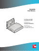
WorldDSL USER MANUAL RATE SELECTABLE HDSL LINE AND DESKTOP UNITS C N LM SY A UTU-701C List 1 Universal Termination Unit Part Number: 150-1422-01C H D SL M AL I/F C LO LP BK EM R Wo G.7 ETU-751C List 1 ETSI Termination Unit Part Number: 150-1432-01C rld 03 DS L HDSL SYNC ALM I/F ALM LOC LPBK REM V.
700-701-100-02 Revision History of This Manual To order copies of this manual, use document number 700-701-100-02. Issue Release Date Revisions Made 1 January 14, 2000 Initial release 2 August 9, 2002 ADC rebrand Copyright August 22, 2002 © 2002 ADC DSL Systems, Inc. All rights reserved. Trademark Information ADC is a registered trademark and WorldDSL is a trademark of ADC Telecommunications, Inc.
700-701-100-02 Using This Manual USING THIS MANUAL The following conventions are used in this manual: • Monospace type indicates screen text. • Keys you press are indicated by small icons such as Y or ENTER . Key combinations to be pressed simultaneously are indicated with a plus sign as follows: CTRL + ESC . • Items you select are in bold. • Three types of messages, identified by icons, appear in text. Notes contain information about special circumstances.
Inspecting Shipment iv 700-701-100-02 August 9, 2002 ETU-701C and ETU-751C List 1
700-701-100-02 Table of Contents TABLE OF CONTENTS Overview ____________________________________________________________________________ 1 Rate Selectable HDSL Unit Firmware...............................................................................................1 EMU Firmware Compatibility ...........................................................................................................2 Application Interface...................................................................................
Table of Contents 700-701-100-02 System Configuration _________________________________________________________________ 25 Maintenance Terminal Connection ................................................................................................. 25 Modem Connection ......................................................................................................................... 26 Logging On......................................................................................................
00-701-100-02 List of Figures LIST OF FIGURES 1. Leased Line Data Application on a Single-pair G.703 Network ....................................................................3 2. UTU-701C Line Unit Front Panel ..................................................................................................................4 3. ETU-751C Desktop Unit Front Panel.............................................................................................................4 4.
List of Figures 700-701-100-02 37. LTU Interface Alarm History Screen ........................................................................................................... 54 38. History HDSL Span 1 Menu ........................................................................................................................ 55 39. 24 Hour History Screen for HDSL Span 1................................................................................................... 55 40.
700-701-100-02 List of Tables LIST OF TABLES 1. Rate Selectable G.703 Unit Characteristics ....................................................................................................2 2. Transmission Ranges with 0 db ETSI Noise ..................................................................................................3 3. Line and Desktop Unit Front Panel Components ...........................................................................................5 4.
List of Tables 700-701-100-02 37. ECA-801 DB25M to DB15F (X.21) Connector Adapter Pinouts................................................................ 66 38. ECA-802 DB9M to RJ-45 Connector Adapter Pinouts ............................................................................... 67 39. ECA-804 DB9M to Four-Position Terminal Block Connector Adapter Pinouts.........................................
700-701-100-02 Overview OVERVIEW ADC® WorldDSL™ offers High-bit-rate Digital Subscriber Line (HDSL) Line Termination Units (LTUs), Network Termination Units (NTUs), Universal Termination Units (UTUs), and ETSI Termination Units (ETUs). The units are shelf and enclosure mounted, providing full-duplex transmission of up to 2.048 Mbps data over one or two twisted pairs of copper wire.
Overview 700-701-100-02 EMU FIRMWARE COMPATIBILITY The EMU-830 Management Unit firmware must be Version 3.22.08 or later to support rate selectable HDSL units. APPLICATION INTERFACE The UTU-701C and ETU-751C provide G.703 interface ports with a rate selectable HDSL payload. The only application mode is Single, indicating single pair. The G.703 E1 application interface conforms with the ITU-T G.703 physical specification and can be configured for an impedance of 75 Ω unbalanced or 120 Ω balanced.
700-701-100-02 Overview Customer Side Network Side UTU-701 (LTU) Exchange Office DTE UTU-701 (NTU) Single Pair HDSL loop HDSL 4 Time Slots HDSL Time Slots 1 through 4 +Time Slots 0 and 16 G.703 (256 kbps) Figure 1. G.703 (384 kbps) 4 Time Slots (256 kbps) Customer DTE PC Leased Line Data Application on a Single-pair G.703 Network HDSL TECHNOLOGY HDSL is the core technology for ADC’s WorldDSL line of LTUs, UTUs, and ETUs.
Overview 700-701-100-02 FRONT AND REAR PANEL COMPONENTS The line and desktop unit front panels are shown in Figure 2 and Figure 3, respectively. The components on these panels are described in Table 3 on page 5 and in Table 4 on page 6. The ETU-751C desktop unit rear panel is shown in Figure 4 on page 7. The components on this panel are described in Table 5 on page 7. The pinouts for the desktop unit rear panel connectors are listed in Table 34 and Table 35 on page 64.
700-701-100-02 Overview Table 3. Line and Desktop Unit Front Panel Components Name Function HDSL SYNC LED Displays synchronization state for the HDSL loop. HDSL ALM LED Displays alarm state for the HDSL loop. I/F ALM LED Displays alarm state for the G.703 data port. LOC LPBK LED Displays local (LOC) loopback state. LOC LPBK Button Activates the local HDSL analog loopback. REM LPBK LED Displays remote (REM) loopback state. REM LPBK Button Activates the remote interface loopback. V.
Overview 700-701-100-02 Table 4 defines the system states indicated by the front panel LEDs. When power is applied to the unit, one of the LEDs listed in Table 4 will always be on. Table 4. Line and Desktop Unit Front Panel LED Indications LED Mode Description HDSL SYNC LED Steady green Slow blinking Off HDSL loop is ready to transmit and receive data across all spans. HDSL loop acquisition is in progress for local span. HDSL loop is not configured.
700-701-100-02 Overview Figure 4. ETU-751C Desktop Unit Rear Panel Table 5. ETU-751C Desktop Unit Rear-Panel Components Item Description D15F 120Ω G.703 connector Connects E1 balanced 120 Ω circuits to the enclosure. BNC 75Ω In/Out G.703 connectors Connects E1 unbalanced 75 Ω circuits to the enclosure. D9F HDSL line connector Connects the HDSL pair to the enclosure. On/Off switch Rocker switch that allows you to turn the externally applied AC power on or off.
Overview 700-701-100-02 WORLDDSL PRODUCT COMPATIBILITY The line and desktop units are compatible with the WorldDSL products listed in Table 6. Table 6.
700-701-100-02 Specifications SPECIFICATIONS HDSL Interface Line Code 2B1Q Line Rate (selectable in increments of 64 kbps) Up to 2048 kbps Protection K.20, K.21 Compliance TS 101 135 Transmission Ranges (± 200 m): Transmission Ranges with 0 dB ETSI Noise Transmission Ranges with No Noise HDSL Line Rate (kbps) 0.4 mm (26 AWG) Single Twisted-Pair Copper Wire 0.51 mm (24 AWG) Single Twisted-Pair Copper Wire 0.4 mm (26 AWG) Single Twisted-Pair Copper Wire 0.
Specifications 700-701-100-02 Alarms Can be individually set to Disabled, Minor, or Major (major alarms actuate the LTU or NTU alarm relay) E1 Interface Loss of Signal (LOS) Loss of Framing (LFA) Alarm Indication Signal (AIS) Remote Alarm Indication (RAI) External Clock Loss of Clock (LOC) HDSL Loop Margin, programmable threshold (MAR) Errored Seconds, programmable threshold (ES) Loss of Sync Word (LOSW) History E1 and HDSL Interface 24-Hour (15-minute intervals) and 7-Day (24-hour intervals) for E
700-701-100-02 Functional Description FUNCTIONAL DESCRIPTION This section provides a functional description of the line and desktop units, including major components, single-pair application mode, alarms, and testing (including monitoring and loopbacks). MAJOR COMPONENTS The major components of the line and desktop units include: • G.
Functional Description 700-701-100-02 G.703 Interface The G.703 interface performs the following functions: • provides a jumper-selectable 75 or 120 Ω DTE interface (see “Installation and Startup” on page 23 for jumper locations) • allocates full or fractional portion of the total 2048 kbps bandwidth to and from the G.703 interface • frames data according to G.704 • inserts an idle code into unused time slots at the G.703 output • recovers timing from the received G.
700-701-100-02 Functional Description Power Sources The line and desktop units receive power from the following sources: • A shelf-mounted UTU-701C receives power from a local source of -36 Vdc to -72 Vdc. • An enclosure mounted UTU-701C receives power from a local source of -36 Vdc to -72 Vdc or from the enclosure’s built-in AC-to-DC power supply (when provided). • The ETU-751C desktop unit receives power from a source of 100 to 240 volt, 50 or 60 Hz, AC power.
Functional Description 700-701-100-02 RATE SELECTABLE APPLICATION MODES AND OPTIONS Applications for single-pair rate-selectable HDSL are those that require transport of voice and data at various rates over various distances on a single pair of wires. Depending on line noise and the HDSL rate selected, spans of up to 7.1 km (4.4 miles) can be deployed without the use of doublers. The HDSL line rate depends on the number of time slots selected.
700-701-100-02 Functional Description Table 7. Typical Structured Mode System Settings Options Setting Application Mode <32 TS (Structured) LTU Interface Primary Timing Source G.703 G.703 Port CRC-4 Mode Enabled Idle Code FF Data Rate / # of TSs 1536 kbps / 24 Beginning TS 1 NTU Interface Primary Timing Source G.703 G.703 Port CRC-4 Mode Enabled Idle Code FF Data Rate / # of TSs 1536 kbps / 24 Beginning TS 1 For applications requiring fractional use of the G.
Functional Description 700-701-100-02 Unstructured Mode When 32 time slots are selected, the line and desktop units automatically operate in the unstructured mode (see “G.704 Framing and Rate Selectable HDSL” on page 17). There is no unstructured menu selection. In the unstructured mode: • There is no G.704 framing. • Time slot 0 is the beginning time slot, and the data rate is fixed at 2048 kbps. • A transparent transmission channel is provided between the local and remote units.
700-701-100-02 Functional Description G.704 Framing and Rate Selectable HDSL Time slots 0 and 16 are always transported in accordance with the G.704 framing standard. Although not used by G.703 to transport data, the rate-selectable HDSL interface treats time slots 0 and 16 as a 128 kbps increase in the HDSL payload rate. For example, when 4 time slots are selected (256 kbps), time slots 0 and 16 are transported along with the selected time slots, 1 though 4.
Functional Description 700-701-100-02 PERFORMANCE MONITORING AND HISTORY The UTU and ETU units provide extensive real time, non-disruptive monitoring of HDSL transmission performance parameters for all units in a circuit. Performance of the user interface ports is also monitored.
700-701-100-02 Functional Description Table 11. HDSL Transmission and Application Interface Alarms Alarm Description HDSL Alarms HDSL alarms include: Margin (MAR) Margin has fallen below threshold set for the HDSL interface. Errored Seconds (ES) Errored seconds count has exceeded threshold set for the HDSL interface. Loss of Sync Word (LOSW) G.703 Alarms Loss of sync word at the HDSL interface. Remains active during restart, but not a cold start. G.
Functional Description Table 12. Loopback 700-701-100-02 Loopbacks Selected at Front Panel Pushbuttons and Console Screens Description The two loopbacks that follow can be selected from the LOC and REM front-panel pushbuttons, the console screens, or the management unit interface.
700-701-100-02 Functional Description Table 13 summarizes the equivalent loopbacks for two different activation methods: • LTU and NTU LOC and REM buttons • console screen Test menus (see “Testing” on page 60 for loopback operation from the Test menus) Table 13.
Inspection, Safety, and Equipment Repair 700-701-100-02 INSPECTION, SAFETY, AND EQUIPMENT REPAIR This section describes the procedures to be followed regarding product inspection, safety, and repair. INSPECTION Open the line or desktop unit shipping carton and inspect the contents for signs of damage. If the equipment was damaged in transit, immediately report the extent of the damage to the transportation company and to ADC (see “Product Support” on page 69).
700-701-100-02 Installation and Startup INSTALLATION AND STARTUP This section describes the installation and startup procedures for the line and desktop units. UTU-701C LINE UNIT INSTALLATION Perform the following steps to install the UTU-701C line unit. The chassis ground of the shelf or remote enclosure receiving these units must be connected to earth ground for protection of the equipment and for safety of personnel. Primary protection for the HDSL line must be provided by the user.
Installation and Startup 700-701-100-02 The line and desktop units will reset and their LEDs will sequence through the startup cycle following any change to the Local Unit Role option. If necessary, log on again by pressing the SPACEBAR several times. ETU-751C DESKTOP UNIT INSTALLATION Perform the following steps to install an ETU-751C desktop unit. 1 Insert the AC power cord into the power cord receptacle on the ETU rear panel.
700-701-100-02 System Configuration SYSTEM CONFIGURATION Each line unit provides a system-wide view of the entire HDSL circuit, including the remote unit. After establishing communication with the remote line card, provisioning information can be set and performance can be monitored from the local unit. If the HDSL link is down, the only parameters that can be changed are those on the local line unit. The LTU overwrites any NTU settings when the link is re-established.
System Configuration 700-701-100-02 To connect and configure a maintenance terminal: 1 Connect a serial cable from the maintenance terminal 9-pin COM port to the line or desktop unit console port connector (Figure 11). Ensure the Data Terminal Ready (DTR) signal from the terminal is connected as the HDSL card will not communicate without it. Data Terminal Ready (DTR) may also be asserted by connecting the DSR output signal (pin 6) to the DTR input (pin 4).
700-701-100-02 System Configuration LOGGING ON To log on to the maintenance terminal console screen: 1 Press the SPACEBAR several times to display the Logon Password screen (Figure 12). Figure 12. Logon Password Screen The ENTER key is the factory default password. If you establish a different password, you must type the new password (single word, no spaces, up to eight characters) on a subsequent log on.
System Configuration 700-701-100-02 CONSOLE SCREEN STRUCTURE The following sections describe the structure of the console screen and how to navigate through its menus and related displays. The structure of the console screen displays and drop-down menus is shown in Figure 14. The names in the console screen menu bar identify each display and menu. The arrows in the menu bar following the Monitor, History, and Config names indicate the presence of a drop-down menu or sub-menu.
700-701-100-02 System Configuration Table 14 describes the drop-down menus selected from the console screen. Table 14. Console Screen Menus Menu Name Function Described in this section Main Display the Main console screen to: • View the circuit configuration • View performance summary information • View alarm summary information “Main Console Screen” on page 46 Monitor Monitor the past 24-hour performance of the LTU interfaces, NTU interfaces, or HDSL spans.
System Configuration 700-701-100-02 READING AND NAVIGATING MENUS The menu and status bars appear on all console screens. The information on the rest of the screen varies depending on the function of the menu or screen. The menu bar displays the name of each menu. Choosing Monitor, History, or Config from the menu bar drops down a menu of available options. When selected, all options on the Monitor drop-down menu, and the Alarm option on the Config drop-down menu, display drop-down submenus.
700-701-100-02 System Configuration Use the keys described in Table 16 to navigate the console screen and its menus: Table 16. Console Screen Navigation Keys Press this Key To Perform this Function Alpha-numeric keys Type the underlined or highlighted letter to select and execute a menu item. For example on the Main console menu, type C to access the Config drop-down menu. Also use these key to enter values in text fields.
System Configuration 700-701-100-02 Config Menu Options Type C at the console screen (Figure 15) to display the Config menu (Figure 16). Table 17 lists the Config menu options and the order of system configuration. Figure 16. Console Screen Config Menu Table 17. Config Menu Options and Recommended Order of System Configuration Use this Option To: See page: Terminal Settings Select the best viewing mode for the console screen. 33 Date and Time Set the system date and time.
700-701-100-02 System Configuration Configure Terminal Settings The console screens use line drawing characters to enclose menu selections and dialog boxes. Because not all maintenance terminals and terminal emulation programs adhere consistently to the VT100 standard, the HDSL card allows you to adjust the display for best results on a given terminal. 1Type at the Config drop-down menu to display the Config Terminal Settings menu (Figure 17). T Figure 17.
System Configuration 700-701-100-02 Configure Date and Time 1Type D at the Config drop-down menu to display the Config Date and Time menu (Figure 18). Figure 18. Config Date and Time Menu 2 Type the date in DD/MM/YY format, then press ENTER . 3 Type the time in HH : MM format (24-hour clock), then press ENTER . The system date and time appear on the status line of the console screen and is useful when viewing alarm histories.
700-701-100-02 System Configuration Change Password 1Type P at the Config drop-down menu to display the Config Change Password menu (Figure 19). Figure 19. Config Change Password Menu 2 Enter a new password (up to eight characters) to change the current system password. 3 Retype the new password (up to eight characters) to confirm its accuracy. When changing the default password ( ENTER ), save the new password in a secure place. A password cannot be recovered if it is forgotten.
System Configuration 700-701-100-02 Configure Circuit ID The circuit ID appears on the status line of each console screen. Choose a unique circuit ID for each HDSL card. 1Type C at the Config drop-down menu to display the Config Circuit ID menu (Figure 20). Figure 20. Config Circuit ID Menu 2Type a new circuit ID (up to 23 characters) to change the current circuit ID.
700-701-100-02 System Configuration Configure System Settings Use the System Settings menu to select and configure system-wide operating parameters. Configure system settings as follows: 1 Type S at the Config drop-down menu to display the Config System Settings menu. Figure 21 shows the Config System Settings menu for the UTU-701C and ETU-751C. Figure 21. 2 Config System Settings Menu Do the following for each system option setting to be changed.
System Configuration 700-701-100-02 Table 18. Field and Options Application Mode Fields and Options Displayed in Config System Settings Menu Description (a) SINGLE HDSL Rate Mode (a) MANUAL HDSL Payload Rate (c) 256kbps/4 Remote Console Access System uses a single-pair of twisted copper wire to transport data. For more information, see “Rate Selectable Application Modes and Options” on page 14. Selects the mode with which the HDSL payload rate will be determined.
700-701-100-02 System Configuration Configure LTU and NTU Interfaces Select and configure the LTU- and NTU-related operating parameters as follows: 1 Type one of the following at the Config drop-down menu to display the Config LTU or NTU Interface menu: • L for the Config LTU Interface menu (Figure 22). • N for the Config NTU Interface menu (Figure 23). Figure 22. Config LTU Interface Menu Figure 23.
System Configuration 2 700-701-100-02 Do the following for each interface option to be changed. Table 19 describes the fields and options displayed in the Config LTU and Config NTU Interface menus. • Use the • Use the ENTER ↑ or the ↓ key to select the sub-menu item to be changed. SPACEBAR to toggle to the appropriate option or type in the correct information, then press to select the option. The settings in boldface type in Table 16 are factory default settings. Table 19.
700-701-100-02 System Configuration Configure Alarms Use the Config Alarms menu to configure LTU and NTU Interface alarm parameters and the HDSL span alarm parameters. When setting alarm parameters for LTUs and NTUs, keep the following rules in mind: • Disabled alarms do not cause LED indications and are not stored in history. Console screen menu alarm history reports are not generated. • Minor alarms cause LED indications and are stored in history.
System Configuration 700-701-100-02 Alarms for LTU and NTU Interface 1 2 Type one of the following at the Config Alarms drop-down menu to display the Config Alarms LTU or Config Alarms NTU Interface menu: • L for the Config Alarms LTU Interface menu (Figure 25) • N for the Config Alarms NTU Interface menu (Figure 26) Config Alarms LTU Interface Menu Figure 26. Config Alarms NTU Interface Menu Do the following for each interface option to be changed.
700-701-100-02 System Configuration Table 20. Fields Displayed in Config Alarms LTU and Config Alarms NTU Interface Menus Field Description Loss of Signal (LOS) Loss of signal at the G.703 input. Loss of Frame Alignment (LFA) Loss of frame alignment at the G.703 input. Receive Alarm Indication Signal (AIS) Alarm indication signal (unframed all ones) received at the G.703 input. Remote Alarm Indication Signal (RAI) Remote alarm indication signal received at the G.703 input (through A-bit).
System Configuration 700-701-100-02 Table 21. Fields Displayed in Config Alarms HDSL Span 1 Menu Field Description Margin (MAR) Selects whether the alarm is disabled (DIS), or enabled and reported as a Minor (MIN) or Major (MAJ) Alarm when the margin falls below the threshold. This indicates a potential degradation of line quality. If an alarm is configured as a protection switch (PSW), it will behave as a Major (MAJ) Alarm, and cause protection switching to engage.
700-701-100-02 3 System Configuration Do one of the following: • Type • Type Y to reset values to factory defaults. The system resets and both LTU and NTU units go through their respective synchronization processes. If loops are down or are in update mode while Set to Factory Dflts is enabled, only the local unit will restart. If the loops are up, both the LTU and NTU will restart. N to keep the current settings. The factory default system settings are listed in Table 22. Table 22.
Viewing Status 700-701-100-02 VIEWING STATUS The following sections describe the screens that display status and system information, such as current alarm status, performance history, product, and configuration information. View status using a maintenance terminal or PC running a terminal emulation program connected to the V.24 (RS-232) console port. See page 25 for instructions on connecting a maintenance terminal or PC.
700-701-100-02 Viewing Status Table 24 describes the fields displayed on the Main console screen. Table 24. Fields Displayed in Main Console Screen Field Description Circuit Configuration G.703 Indicates the interface standard for G.703 data port. n TS Indicates the number of time slots (n) mapped to the G.703 interface. Timing Indicates the primary source the unit uses for clock synchronization: EXT External 2.048 MHz clock. G.703 G.703 port receive clock.
Viewing Status 700-701-100-02 MONITOR MENU The Monitor menu contains the following options: • LTU Interface screen that displays the 24 hour and cumulative count of errors at the LTU G.703 port. • NTU Interface screen that displays the 24 hour and cumulative count of errors at the NTU G.703 port. • HDSL Span 1 screen that displays the circuit performance and 24-hour error counts at the HDSL span 1 interface. Type 0 at the console screen to display the Monitor menu (Figure 30). Figure 30.
700-701-100-02 Viewing Status Monitor LTU Interface Screen At the Monitor menu (Figure 30), type L to display the Monitor LTU Interface screen (Figure 31). Table 25 describes the fields displayed in the Monitor LTU and Monitor NTU Interface screens. Figure 31. Table 25. Field Monitor LTU Interface Screen Fields Displayed in Monitor LTU and Monitor NTU Interface Screens Description G.
Viewing Status 700-701-100-02 Monitor NTU Interface Screen At the Monitor menu (Figure 30), type N to display the Monitor NTU Interface screen (Figure 32). The fields displayed in the Monitor NTU Interface screen are identical to those displayed in the Monitor LTU Interface screen (see Table 25 on page 49). Figure 32.
700-701-100-02 Viewing Status Monitor HDSL Span 1 Screen The HDSL Span 1 screen (Figure 33) displays the circuit performance and 24-hour error counts at the HDSL span 1 interface. A span is defined as the link between two HDSL units (that is, from an LTU to an NTU) which, in this case, is comprised of a single loop (that is, one twisted-copper pair). The values under the LTU-1 column represent HDSL Span 1 as measured by the LTU.
Viewing Status 700-701-100-02 HISTORY MENU The History menu contains the following status screens: • LTU/NTU Interfaces that display alarm performance history for the LTU and NTU interface. • HDSL Span that displays 24-hour, 7-day, and alarm performance history for the HDSL span. The History menu also provides the option to clear the 24-hour, 7-day, and alarm history screens. This option is described on page 58. Type H to select the History menu (Figure 34). Figure 34.
700-701-100-02 Viewing Status LTU and NTU Interface Performance History Screens At the History menu (Figure 34), type L to select the History LTU Interface menu (Figure 35). Figure 35. At the History menu (Figure 34), type N History LTU Interface Menu to select the History NTU Interface menu (Figure 36). Figure 36.
Viewing Status 700-701-100-02 Only the Alarm History screen is available for the LTU and NTU interfaces. The 24 Hour and 7 Day History screens, as well as the Alarm History screen, are available for HDSL Span 1. LTU and NTU Interface Alarm History Screens At the History LTU or History NTU Interface menu, type the LTU Interface Alarm History screen is shown in Figure 37. Figure 37. A key to select an Alarm History status screen.
700-701-100-02 Viewing Status HDSL Span Performance History Screens At the History menu (Figure 34), type 1 to select the History HDSL Span 1 menu (Figure 38). Figure 38. History HDSL Span 1 Menu The History HDSL Span 1 menu contains three viewing options: • 24 Hour History • 7 Day History • Alarm History HDSL Span 1 24 Hour History Screen At the History HDSL Span 1 menu (Figure 38), type Span 1 (Figure 39). Figure 39.
Viewing Status 700-701-100-02 The 24 Hour History screen for HDSL Span 1 contains three columns of data that show (from left to right) the: • Starting time of each 15-minute interval. • Number of ES/UAS at the LTU end of the HDSL span (LTU-1) for each interval. A dash (-) represents a count of zero. • Number of ES/UAS at the NTU end of the HDSL span (NTU-1) for each interval. A dash (-) represents a count of zero.
700-701-100-02 Viewing Status HDSL Span 1 Alarm History Screens At the History HDSL Span 1 menu (Figure 38), type Span 1 (Figure 41). Figure 41. A to select the Alarm History status screen for HDSL Alarm History Status Screen for HDSL Span 1 Table 28 describes the four columns of data contained in each HDSL Span Alarm History screen. Table 28.
Viewing Status 700-701-100-02 Clear History Screens Use the following options to clear the 24 Hour, 7 Day, or Alarm History status screens: • Clr 24 Hr Hist: clears all of the 24-hour history error counters • Clr 7 Day Hist: clears all of the 7-day history error counters • Clr Alarm Hist: clears all alarm history logs To clear the status screens: 1Select the alarm history option to be cleared with the message displays: ↑ and ↓ keys, then press ENTER .
700-701-100-02 Viewing Status Table 29. Inventory Screen Data Field Description Network Diagram Displays the configuration of the LTU or NTU circuit. Product Displays the model numbers of the LTU, NTU, and any doubler units that comprise the channel. List # Displays the LTU, NTU, and doubler unit list numbers, which identify the particular unit versions. H/W Cfg Displays the LTU, NTU, and doubler unit hardware configuration level.
Testing 700-701-100-02 TESTING T From the main console screen (Figure 29), type loopback and BER tests (Figure 43). Figure 43. to display the Test menu from which you can set and run Test Menu Screen Table 30 on page 61 lists the Test menu options. Table 31 lists the fields displayed in the Bit Error Rate (BER) section of the test menu. Loopbacks remain active until the timeout elapses or the configuration changes.
700-701-100-02 Testing Table 30. Test Menu Options Operating Option Default Setting Network Diagram Shows the loopback position and direction when the loopback is enabled and active. Lpbk Dir Selects one of three loopback direction modes: OFF No loopbacks are active. NETWORK The loopback selected in Loopback Position is directed toward the network equipment connected to the LTU.
Firmware Download Utility 700-701-100-02 FIRMWARE DOWNLOAD UTILITY The Firmware Download Utility is a separate program and is not available from the console screen menus. This section describes the ETSI Firmware Download utility and how to use it to upgrade the line and desktop unit firmware. The ETSI Firmware Download utility is a program you can run on a PC to download new firmware to the LTU or NTU by connecting a standard RS-232 interface cable to the unit front panel V.24 console port.
700-701-100-02 Firmware Download Utility Initiate the Download and Navigate the Menus To initiate the download process, go to the DOS prompt and type: dnl. Table 32 describes ETSI Firmware User Selectable Download Menu Options. Table 32. ETSI Firmware User Selectable Download Menu Options Option Description PORT Provides support for two communication ports: COM1 at Hex 3F8 COM2 at HEX 2F8 SPEED Supports Standard (9600 bit/s), Medium (19.2K kbps), Fast (38.4 kbps), Faster (57.6 kbps) and TURBO (115.
Reference Information 700-701-100-02 REFERENCE INFORMATION This section lists the pinouts for the ETU-751C rear panel connectors and the ECA-80x connector adapters. ETU-751C CONNECTOR PINOUTS The pinouts for the ETU-751C rear panel connectors are listed in Table 34 and Table 35. Table 34.
700-701-100-02 Reference Information ECA-800 CONNECTOR ADAPTER (DB25M TO M34F FOR V.35) The ECA-800 connector adapter (Figure 45) converts the DB25F data port connector on the desktop unit rear panel to a standard V.35 34-pin female connector. Table 36 lists the ECA-800 pinouts. A C E H K M P S U W Y AA EE KK CC HH MM Figure 45. B D F J 14 L N R T V X BB Z DD 25 FF LL JJ 13 NN ECA-800 DB25M to M34F (V.35) Connector Adapter, Part Number 150-1470-01 Table 36.
Reference Information 700-701-100-02 ECA-801 CONNECTOR ADAPTER (DB25M TO DB15F FOR X.21) The ECA-801 connector adapter (Figure 46) converts the DB25F data port connector on the desktop unit rear panel to a standard X.21 15-pin female connector. Table 37 lists the ECA-801 pinouts. 1 14 1 9 15 8 25 Figure 46. 13 ECA-801 D25M to DB15F (X.21) Connector Adapter, Part Number 150-1470-01 Table 37. ECA-801 DB25M to DB15F (X.21) Connector Adapter Pinouts DB25M Connector DB15F (X.
700-701-100-02 Reference Information 1 8 6 9 Figure 47. 1 5 ECA-802 DB9M to RJ-45 Connector Adapter, Part Number 150-1472-01 Table 38. ECA-802 DB9M to RJ-45 Connector Adapter Pinouts DB9M Connector RJ-45 Connector Signal Pin (a) Pin (a) Signal HDSL Loop 1 (Ring) 4 1 HDSL Loop 1 (Ring) HDSL Loop 1 (Tip) 9 2 HDSL Loop 1 (Tip) HDSL Loop 2 (Ring) 1 4 HDSL Loop 2 (Ring) HDSL Loop 2 (Tip) 6 5 HDSL Loop 2 (Tip) (a) Pins 1, 6, 4, and 5 not used on single-pair HDSL cards.
Reference Information 700-701-100-02 ECA-804 CONNECTOR ADAPTER (DB9M TO FOUR-POSITION TERMINAL BLOCK) The ECA-804 connector adapter (Figure 48) converts the DB9F HDSL line connector on the desktop unit rear panel to a four-position terminal-block style connector. Table 39 lists the ECA-804 pinouts. 1 2 3 4 Figure 48. 6 9 1 5 ECA-804 DB9M to Four-Position Terminal Block Connector Adapter, Part Number 150-1474-01 Table 39.
700-701-100-02 Product Support PRODUCT SUPPORT ADC Customer Service Group provides expert pre-sales and post-sales support and training for all its products. Technical support is available 24 hours a day, 7 days a week by contacting the ADC Technical Assistance Center at the number listed below. Sales Assistance 800.366.3891 ext. 73000 (USA and Canada) or 952.917.3000 Fax: 952.917.3237 • Quotation Proposals Systems Integration 800.366.3891, ext. 73000 (USA and Canada) or 952.917.
Abbreviations 700-701-100-02 ABBREVIATIONS AIS Alarm Indication Signal LL Local Loopback ALM Alarm LOC Local ANSI American National Standards Institute LOC Loss of Clock AWG American Wire Gage LOSW Loss of Sync Word BER Bit Error Rate LPBK Loopback C Centigrade LTU Line Termination Unit COM Communication M34F M-type 34-pin Female Connector CRC Cyclic Redundancy Check MAR Margin CTS Clear To Send Mbps Megabits per second D15F D-type 15-pin Female Connector MHz Megaher
CERTIFICATION AND WARRANTY DIRECTIVE EN300 386-2 COMPLIANCE To indicate compliance with EN300 386-2, these products have been affixed with the CE mark. LIMITED WARRANTY ADC DSL Systems, Incorporated (“ADC”) warrants that, for a period of sixty (60) months from the date of shipment, the hardware portion of its products will be free of material defects and faulty workmanship under normal use.
ADC DSL Systems, Inc. 14402 Franklin Avenue Tustin, CA 92780-7013 Tel: 714.832.9922 Fax: 714.832.9924 Technical Assistance ISO 9001/TL 9000 DOCUMENT: 700-701-100-02 ´,JE¶1l¨ DNV Certification, Inc.