USER MANUAL Soneplex DS3 Loop Extender (D3LX) CO Module Product: D3LXC-FCA100, D3LXC-SCA100 CLEI Code: SOCPG2GB, SOCPG2KB Soneplex DS3 Loop Extender (D3LX) RMT Module Product: D3LXR-FCA100, D3LXR-SCA100 CLEI Code: SOCPG2HB, SOCPG2JB
LTPS-UM-8013-03 Revision History of This Manual To order copies of this document, use document catalog number LTPS-UM-8013-03.
LTPS-UM-8013-03 Using This Manual USING THIS MANUAL The following conventions are used in this manual: • Monospace type indicates screen text. • Keys you press are indicated by small icons such as Y or ENTER . Key combinations to be pressed simultaneously are indicated with a plus sign as follows: CTRL + ESC . • Items you select are in bold. • Three types of messages, identified by icons, appear in text. Notes contain information about special circumstances.
Inspecting Shipment iv LTPS-UM-8013-03 August 30, 2002 D3LX CO and RMT Modules
LTPS-UM-8013-03 Table of Contents TABLE OF CONTENTS Overview ____________________________________________________________________________ 1 Front-Panel Description________________________________________________________________ 3 Protection Switching ..........................................................................................................................4 Automatic Switching ...........................................................................................................
Table of Contents LTPS-UM-8013-03 Performance Monitoring ................................................................................................................. 29 Performing System Maintenance .................................................................................................... 30 Logging Off ..................................................................................................................................... 31 Removing D3LX Modules ...............................
LTPS-UM-8013-03 List of Figures LIST OF FIGURES 1. D3LX CO and D3LX RMT Modules.............................................................................................................1 2. System Overview............................................................................................................................................2 3. D3LX CO Front Panel....................................................................................................................................3 4.
List of Tables LTPS-UM-8013-03 LIST OF TABLES 1. D3LX Front-Panel Description and Status LEDs .......................................................................................... 4 2. Tip and Ring Assignments for Protection Switching Applications ............................................................... 8 3. Chassis Port Description .............................................................................................................................. 19 4.
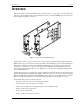
LTPS-UM-8013-03 Overview OVERVIEW The Soneplex® DS3 Loop Extender (D3LX) modules shown in Figure 1 are a pair of fiber-optic units that provide DS3 service. The D3LX CO resides at the Central Office (CO) site, and the D3LX RMT resides at the Customer Premises Equipment (CPE) or remote site. D3LX CO D3LX RMT STATU S STATU S FAR END FAR END DS3 STATU S ENAB LE DS3 STATU S ENAB LE DS3 ONLI NE DS3 ONLI NE Figure 1.
Overview LTPS-UM-8013-03 CO - Local DS3 out (transmit) 1 2 3 4 5 6 7 15 16 17 18 19 20 21 21 6 5 4 3 2 1 20 19 18 17 16 15 BNC panel - front DS3 in (receive) DS3 out DS3 in BNC panel - rear ADC adapter cables PORT 2 D3LX CO DTE RS-232 PORT 3 DTE RS-232 SHIELD GND STATUS FRAME GND FAR END 2-4 T L1 R T1 L2 R1 DS3 STATUS R=FAULT G=O.K.
LTPS-UM-8013-03 Front-Panel Description FRONT-PANEL DESCRIPTION Figure 3 shows the D3LX CO front panel. Table 1 on page 4 describes the LEDs and other front-panel components. For pinout diagrams of the D3LX card-edge connector, refer to “D3LX Card-Edge Connector” on page 38. D3LX CO STATUS FAR END Status LEDs DS3 STATUS Enable pushbutton ENABLE Online status LED DS3 ONLINE OPT Fiber-optic status LEDs R=FAULT G=O.K.
Front-Panel Description LTPS-UM-8013-03 Table 1. D3LX Front-Panel Description and Status LEDs Name Function LEDs The LEDs can report the following conditions: STATUS FAR END Activity Color Status Off Not lit Blown fuse On (solid) Green Normal operation. On (solid) Yellow Module initializing or performing self test diagnostics or LED test. On (solid) Red Module fault detected. Off Not lit Remote alarms inactive (no alarm). On (solid) Yellow Remote alarm on D3LX CO.
LTPS-UM-8013-03 Front-Panel Description Automatic Switching The 1:1 (Line) Protect mode transmits identical traffic across two parallel systems. The working and protect D3LX modules provide Automatic Protection Switching (APS) compatible with the remote D3LX module. APS is non-revertive and bidirectional and may be forced or disabled through the front-panel pushbuttons or the SCU software.
Preparing to Install D3LX Modules LTPS-UM-8013-03 PREPARING TO INSTALL D3LX MODULES Prior to installing D3LX modules in chassis confirm that: 6 • chassis are installed for each module (an LEC for the D3LX CO and a Four-Position Remote Terminal Cabinet or Two-Position QLX Remote BNC Chassis for the D3LX RMT). • a BNC Patch Panel with ADC adapter cables is installed in the CO rack and at the remote site. For more information about this operation, refer to “Installing the BNC Panel” on page 7.
LTPS-UM-8013-03 Installing the BNC Panel INSTALLING THE BNC PANEL OVERVIEW The ADC BNC Panel consists of 14 pairs of 75Ω BNC connectors that are part of a system that converts an electrical DS3 circuit at the CO site into an optical signal that uses WDM to transmit a signal across one single-mode fiber to a CPE site. The BNC Panel can support 7 working D3LX lines and 7 protection D3LX lines.
Installing the BNC Panel LTPS-UM-8013-03 6 From the rear of the panel, connect the coax end of an ADC adapter cable to the DS3 OUT (transmit). connector. The connector number must match the connector number on the front of the panel. 7 Connect the wire-wrap conversion block end of the same ADC adapter cable to the T and R EQUIP wire-wrap posts on the back of the LEC as shown in Figure 4 on page 8.
LTPS-UM-8013-03 Installing a D3LX CO Module in an LEC INSTALLING A D3LX CO MODULE IN AN LEC Avoid exposure to invisible laser radiation. • Do not look into the ends of any optical fiber or directly into the module fiber connectors as exposure to invisible laser radiation may result. • Use a meter to verify active fibers. • Do not insert module edge connectors into the chassis connectors before connecting the optical fiber to the module.
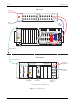
Installing a D3LX CO Module in an LEC LTPS-UM-8013-03 Fiber patch cord FiberGuide vertical duct Heat baffle/fiber management panel Figure 5. Routing the Fiber Patch Cord 4 Locate the mounting slots designated for the D3LX CO modules in the chassis. 5 Refer to Figure 6 on page 11 for D3LX CO module locations chassis and slot corresponding to the DS3 signal. – If no protection switching is required, proceed to the next step.
LTPS-UM-8013-03 Installing a D3LX CO Module in an LEC Use #1 mounting slots for working D3LX units Use #3 mounting slots for protect D3LX units 1-3 2-3 1-1 2-1 1 2 D3LX CO 3-3 3-1 3 4-3 5-3 4-1 5-1 4 5 6-3 6-1 7-3 7-1 SCU APU 6 7 S C U D3LX CO STATUS STATUS STATUS FAR END FAR END O S S CR ETH MJ X.25 MN DS3 STATUS DS3 STATUS R=FAULT G=O.K. R=FAULT G=O.K.
Installing a D3LX CO Module in an LEC LTPS-UM-8013-03 Fiber patch cord Fiber clip D3LX CO Figure 7. Installing the D3LX CO 9 After removing the protective cover from a fiber patch cord, clean the fiber-optic connector and adapter as directed in “Appendix B - Cleaning and Mating Fiber-Optic Systems” on page 39. POWER VERIFICATION Verification of Electrical DS3 Power Level 1 Apply power to the D3LX CO. 2 Attach the fiber patch cord from the D3LX CO to a meter.
LTPS-UM-8013-03 Installing a D3LX CO Module in an LEC Verification of D3LX CO Optical Power 1 Connect an attenuator in series: • Connect a patch cord from the meter to the attenuator. • Connect a meter patch cord from the attenuator to the module. 2 Using the retaining latch, press the module into the chassis until it is properly seated. 3 Is the STATUS indicator lit green? 4 • If Yes, continue to next step. • If No, repeat steps 1 through 3 with a new D3LX CO module.
Installing a D3LX RMT Module in a Remote Cabinet LTPS-UM-8013-03 INSTALLING A D3LX RMT MODULE IN A REMOTE CABINET Avoid exposure to invisible laser radiation. • Do not look into the ends of any optical fiber or directly into the module fiber connectors as exposure to invisible laser radiation may result. • Use a meter to verify active fibers. • Do not insert module edge connectors into the chassis connectors before connecting the optical fiber to the module.
LTPS-UM-8013-03 Installing a D3LX RMT Module in a Remote Cabinet 3 Locate the mounting slots designated for the D3LX RMT modules in the chassis. If protection switching is required, a working module installs in the first slot of a quad group, such as 1-1 or 2-1. The protection module installs in the slot to the right of the working module, slot 1-2 or 2-2. 4 Refer to Figure 9 for D3LX RMT module locations chassis and slot corresponding to the DS3 signal.
Installing a D3LX RMT Module in a Remote Cabinet LTPS-UM-8013-03 TWO-POSITION QLX REMOTE BNC CHASSIS INSTALLATION To install first the working module, and then the protect module (if installing D3LX RMT modules in protection switching applications): LMPTST/ APS RESET G=ONLINE OFF=OFFLINE FAIL BER LOCKOUT FORCE DS3 ONLINE OPT C R A F T D3RCAM APS R=FAULT G=O.K.
LTPS-UM-8013-03 Installing a D3LX RMT Module in a Remote Cabinet Verification of Optical Power 1 Connect an attenuator in series: • Connect a patch cord from the meter to the attenuator. • Connect a meter patch cord from the attenuator to the module. 2 Using the retaining latch, press the module into the chassis until it is properly seated. 3 Is the STATUS indicator lit green? 4 • If Yes, continue to next step. • If No, repeat steps 1 through 3 with a new D3LX RMT module.
Provisioning 15 LTPS-UM-8013-03 Store the remaining slack fiber on the left side of the fiber management enclosure within the remote cabinet, leaving 5 to 6 inches of slack fiber above the upper card guide to provide a service loop. PROVISIONING In D3LX systems, provisioning occurs automatically if a remote module is installed. In the event that a remote module is not installed or properly functioning, refer to the manual provisioning process below.
LTPS-UM-8013-03 Setting Up System Options OTHER PROVISIONING CONSIDERATIONS Alarm Setting During Provisioning The D3LX generates alarms on conditions occurring in the D3LX CO modules DS3 facility. The severity of the alarm conditions as Critical, Major, Minor, or Event is selected while provisioning. The alarms are handed off to an Alarm Processing Unit (APU) which acts as an interface between the D3LX modules and the customer alarm monitoring equipment.
Setting Up System Options LTPS-UM-8013-03 • 9600 baud • No parity • 8 data bits • 1 stop bit • Hardware flow control to OFF Maintenance terminal Serial COM port LEC Craft port Interface cable Figure 11. Connecting a Maintenance Terminal to the SCU The default port configuration for the SCU craft port is CRAFT. Ports 2 and 3 must be configured for CRAFT before the craft interface may be accessed via these ports. 5 At the maintenance terminal, press ENTER .
LTPS-UM-8013-03 5 Setting Up System Options At the maintenance terminal, press ENTER . The Enter User Name field appears. Maintenance terminal Serial COM port STAT US C R A F T RESE T Four-position remote terminal chassis Craft port Interface cable Figure 12.
Setting Up System Options LTPS-UM-8013-03 NAVIGATING THROUGH CRAFT INTERFACE MENUS Many of the operations that follow require the use of the craft interface. To select a menu from the craft interface, do one of the following: • Press the number of the menu. • Use the ← → arrow keys to select the menu and press ENTER . Table 4 summarizes the navigational keys, which are also listed in the on-screen Help menu. Table 4.
LTPS-UM-8013-03 Local Configuration LOCAL CONFIGURATION A D3LX system can be configured locally by an SCU (version 3.7 or later) with a D3LX CO module in an LEC. It can also be configured remotely by a D3RCAM with a D3LX RMT module installed in a remote chassis. See “Remote Configuration” on page 33 for the procedure configuring remotely using the D3RCAM. The following details the local configuration procedure. CONFIGURING THE D3LX SYSTEM THROUGH THE SCU 3.
Local Configuration LTPS-UM-8013-03 Press CTRL + A for assistance when making selections. 4 Configure the fields as detailed in the Table 5 and assign the selections by pressing 5 Repeat Steps 2 through 5 for each D3LX system installed in the chassis. Table 5. Field Name Type Unit Equip State Toggle Unit Service State Toggle Unit Protect State Toggle Optical Service State Toggle ENTER . D3LX CO Configuration Fields–SCU V3.
LTPS-UM-8013-03 Local Configuration Table 5. Field Name Housekeeping Labels 1 and 2 Type Input D3LX CO Configuration Fields–SCU V3.7 or later (Continued) Options Description Enter up to 8 alphanumeric characters. Default Enter the remote housekeeping alarm label you SCU V3.7 = Blank want for each field; the fields can be edited to create customized labels.
Local Configuration LTPS-UM-8013-03 Figure 14. Table 6.
LTPS-UM-8013-03 Local Configuration DISPLAYING D3LX STATUS 2. Display Status Use this procedure to display the status of both working and protect modules in local and remote sites. 5. Display D3LX Status 1 From the Main menu, select 2. Display Status. 2 From the Alarms menu, select 5. Display D3LX Status (as shown in Figure 16). 3 Use SPACEBAR , ← , → , ↓ , and ↑ to select the group and slot to display. Figure 15.
Local Configuration LTPS-UM-8013-03 VIEWING LOOPBACK STATUS AND PERFORMING LOOPBACK COMMANDS Use this procedure to view loopbacks and send loopback commands for a specific D3LX system. 4. Loopback Status Commands 1. High/Low Speed Loopback Status Commands 1 From the Main menu, select 6. System Maintenance. 2 From the System Maintenance menu, select 4. Loopback Status Commands. 3 From the Loopback Status/Commands menu, select 1.
LTPS-UM-8013-03 Local Configuration PERFORMANCE MONITORING 7. Performance Maintenance Use this procedure to monitor the performance of modules on both the near and far end of D3LX systems. 1 From the Main menu, select 7. Performance Monitoring. 2 From the Performance Monitoring menu, select DS3/E3 PM Configuration (as shown in Figure 17). 3 In PM Reports, select DS3/E3 Far End PM Configuration. 1. PM Configuration 2.
Local Configuration LTPS-UM-8013-03 PERFORMING SYSTEM MAINTENANCE Use this procedure to perform the system maintenance commands listed. 1 From the Main menu, select 6. System Maintenance. 2 From the System Maintenance menu, select • • • • 3 1. Force/APS Commands, and then select 1. Commands for Optical Facilities to view and force line protection for the available circuits, 2. Reset/LED Test Commands to reset the selected D3LX module or verify that its LEDs are working properly, 6.
LTPS-UM-8013-03 Local Configuration Figure 18. System Maintenance–Trouble Isolation Screen Shown LOGGING OFF To log off from anywhere on the system during a Telnet session, press D3LX CO and RMT Modules August 30, 2002 CTRL + D.
Local Configuration LTPS-UM-8013-03 REMOVING D3LX MODULES D3LX CO STAT US FAR DS3 END STAT US ENAB LE DS3 ONLI NE LEC Optical receptical Optical connector Fiber patch cord D3LX module Figure 19. Removing a D3LX Module–D3LX CO Shown Do not look into the ends of any optical fiber or into any plug-in module connector. Exposure to invisible laser radiation may cause permanent eye damage. A meter should be used to verify active fibers.
LTPS-UM-8013-03 Remote Configuration REMOTE CONFIGURATION Use the D3RCAM craft interface system menu to view or edit the configuration for each D3LX RMT module in the chassis. This menu can also be used to equip, provision, assign thresholds, and assign service state. The D3RCAM Configuration menu is shown in Figure 22 on page 34. 1 Connect a maintenance terminal to the craft port on the D3RCAM front panel.
Remote Configuration LTPS-UM-8013-03 D3RCAM MENU The D3RCAM Main Menu (as shown in Figure 21) displays following configuration options: Unit Configuration Display Status Alarms Display Active Alarms Display Shelf Status Display Alarm Summary Display D3LX Status System Date/Time System Maintenance Help Protection Switch Status/Commands D3LX Group 1 D3LX Group 2 Display Alarm History Reset/LED Test Command Clear Alarm History Execute ACO (Alarm Cut-Off) Loopback Status/Commands Display Invento
LTPS-UM-8013-03 Remote Configuration 1 From the Main menu, select 3. Unit Configuration. 2 Within the Unit Configuration screen (see Figure 22 on page 34), select the Group number that corresponds to the D3LX circuit you want to configure, based on the module’s position in the remote unit. 3 Select each field parameter and move from field to field as shown in Table 7. Assign the selections by pressing ENTER .
Troubleshooting LTPS-UM-8013-03 TROUBLESHOOTING Before the system tests are started, the fiber-optic network and DS3 lines at both ends must be connected. The STATUS and DS3 ONLINE LEDs should be illuminated green. Table 8 is intended as an aid in localizing trouble. If trouble is encountered with the operation of the D3LX, verify that all installer connections are correct and that the options are configured properly. If technical assistance is required, refer to “Appendix C - Product Support” on page 41.
LTPS-UM-8013-03 Appendix A - Specifications APPENDIX A - SPECIFICATIONS Table 9.
Appendix A - Specifications LTPS-UM-8013-03 D3LX CARD-EDGE CONNECTOR Figure 23 shows the pin assignments of the card-edge connector on the D3LX card. Active pins are highlighted in black.
LTPS-UM-8013-03 Appendix B - Cleaning and Mating Fiber-Optic Systems APPENDIX B - CLEANING AND MATING FIBER-OPTIC SYSTEMS The performance of a fiber-optic system is mainly dependent on the fiber-optic connector cleaning procedures performed before installation. Clean all connectors and adapters before making any connections.
Appendix B - Cleaning and Mating Fiber-Optic Systems LTPS-UM-8013-03 MATING Mate the SC and FC connectors by inserting the connector into the adapter and aligning the connector key with the adapter key slot as follows: 40 • FC connectors—Align the housing key with the slot in the adapter. Push the connector into the adapter and screw the threaded cap clockwise onto the adapter to complete the connection. • SC connector—Align the housing key with the slot in the adapter.
LTPS-UM-8013-03 Appendix C - Product Support APPENDIX C - PRODUCT SUPPORT ADC Customer Service Group provides expert pre-sales and post-sales support and training for all its products. Technical support is available 24 hours a day, 7 days a week by contacting the ADC Technical Assistance Center. Sales Assistance 800.366.3891 extension 73000 (USA and Canada) 952.917.3000 Fax: 952.917.3237 • Quotation Proposals Systems Integration 800.366.3891, extension 73000 (USA and Canada) 952.917.
Appendix D - Abbreviations LTPS-UM-8013-03 APPENDIX D - ABBREVIATIONS A APS: Automatic Protection Switching APU: Alarm Processing Unit ATM: Asynchronous Transport Mode B BER: Bit Error Rate BNC: Bayonet-Locking Connector C CO: Central Office CPE: Customer Premises Equipment D DCE: Data Communication Equipment DTE: Data Terminal Equipment E ESD: Electrostatic Discharge I IS: In Service L LBO: Line Build Out LEC: Loop Extender Chassis LMPTST: Lamp Test LOF: Loss-Of-Frame O OOS:
CERTIFICATION AND WARRANTY FCC CLASS A COMPLIANCE This equipment has been tested and found to comply with the limits for a Class A digital device, pursuant to Part 15 of the FCC Rules. These limits are designed to provide reasonable protection against harmful interference when the equipment is operated in a commercial environment.
ADC DSL Systems, Inc. 14402 Franklin Avenue Tustin, CA 92780-7013 Tel: 714.832.9922 Fax: 714.832.9924 Technical Assistance Tel: 800.366.3891 x73223 Fax: 952.917.3244 ISO 9001/TL 9000 DOCUMENT: LTPS-UM-8013-03 ´,HS¶8N¨ DNV Certification, Inc.