
Installation guide


Table Of Contents
- About This Guide
- Hardware Overview
- Preparing for Installation
- Rack-Mounting the System
- Installing Modules
- Cabling the System
- Powering On and Powering Off
- Configuring Network Access
- System Specifications and Compliance
- Martek Power Supply
- Wiring Diagrams
- Glossary
- Index
ADC Telecommunications, Inc.
122 C
HAPTER 5: CABLING THE SYSTEM
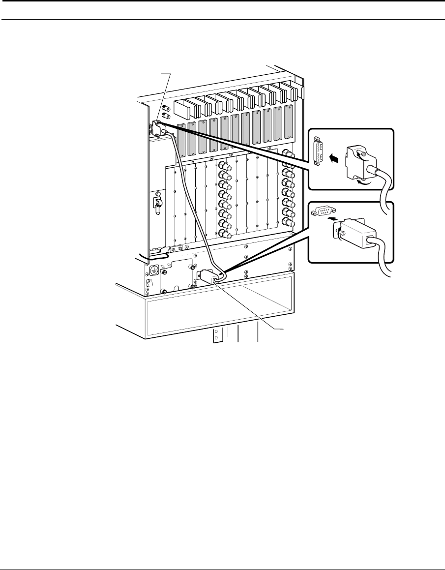
Figure 5-20 shows the cabling of the fan tray to the Alarms In DB-15
connector on the rear chassis panel using the 2-way cable.
Figure 5-20 Cabling for Fault Reporting with 2-way Cable
BAC_55A
J11
J10
J9
J8
J7
J6
J5
J4
J3
J2
J1
To
Earth
Ground
Alarms
In
TAC
Cable