
Installation guide


Table Of Contents
- About This Guide
- Hardware Overview
- Preparing for Installation
- Rack-Mounting the System
- Installing Modules
- Cabling the System
- Powering On and Powering Off
- Configuring Network Access
- System Specifications and Compliance
- Martek Power Supply
- Wiring Diagrams
- Glossary
- Index
Cuda 12000 IP Access Switch Installation Guide
Connecting Power 117
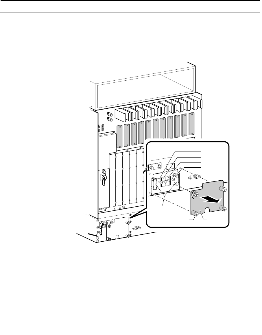
3. Remove the power connector cover located on the rear panel of the fan
tray unit by loosening the four screws that secure the cover, as shown in
Figure 5-17. The power connector unit consists of four threaded power
studs and two slow-blow class 2 fuse cartridges, also shown in
Figure 5-17.
Figure 5-17 Fan Tray Power Connectors
4. To connect the first (A) power source, do the following:
■ Connect the source wire from the first power source to the power
terminal labelled 48 V (A) Feed, as shown in Figure 5-18.
and
■ Connect the return wire from the first power source to the power
terminal labelled 48 V (A) RTN, as shown in Figure 5-18.
■ If you are connecting a second power source, go to the next step. If
your are only connecting the single power source, go to 6..
BAC_35D
J11
J10
J9
J8
J7
J6
J5
J4
J3
J2
J1
To
Earth
Ground
Power Studs (4)
48 V (A) Feed
48 V (A) RTN
48 V (B) RTN
48 V (B) Feed
Power
Connector
Cover
Captive
Screws (4)
2.5A 250V
Slow-Blow
Fuse (2)