ADCP-75-214 Issue 2 September 2006 ClearGain® 1800 MHz and 2100 MHz Dual Inline Tower Mounted Amplifier System User Manual 1383772 Rev A
ADCP-75-214 • Issue 2 • September 2006 • Preface COPYRIGHT © 2006, ADC Telecommunications, Inc. All Rights Reserved REVISION HISTORY ISSUE DATE REASON FOR CHANGE 1 06/2006 Original 2 09/2006 Add support for 1800MHz System TRADEMARK INFORMATION ADC and ClearGain are registered trademarks of ADC Telecommunications, Inc. DISCLAIMER OF LIABILITY Contents herein are current as of the date of publication. ADC reserves the right to change the contents without prior notice.
ADCP-75-214 • Issue 2 • September 2006 • Preface TABLE OF CONTENTS Content Page ABOUT THIS MANUAL . . . . . . . . . . . . . . . . . . . . . . . . . . . . . . . . . . . . . . . . . . . . . . . . . . . . . . . . . . . . . . . . . . . . . . . . . v ADMONISHMENTS . . . . . . . . . . . . . . . . . . . . . . . . . . . . . . . . . . . . . . . . . . . . . . . . . . . . . . . . . . . . . . . . . . . . . . . . . . . v Certification . . . . . . . . . . . . . . . . . . . . . . . . . . . . . . . . . . . . . . . . . .
ADCP-75-214 • Issue 2 • September 2006 • Preface Blank Page iv © 2006, ADC Telecommunications, Inc.
ADCP-75-214 • Issue 2 • September 2006 • Preface ABOUT THIS MANUAL This document describes the ADC ClearGain 1800 and 2100 MHz Dual Inline Tower Mounted Amplifier (TMA) Systems and provides complete instructions for installing these products on a communications tower. ADMONISHMENTS Important safety admonishments are used throughout this manual to warn of possible hazards to persons or equipment. An admonishment identifies a possible hazard and then explains what may happen if the hazard is not avoided.
ADCP-75-214 • Issue 2 • September 2006 • Preface LIST OF ACRONYMS AISG – Antenna Interface Standards Group ANT – Antenna AWG – American Wire Gauge BTS – Base Transceiver Station LED – Light Emitting Diode LNA – Low Noise Amplifier MHU – Masthead Unit OOK – On/Off Key PDU – Power Distribution Unit RET – Remote Electrical Tilt RF – Radio Frequency TMA – Tower Mounted Amplifier Page vi © 2006, ADC Telecommunications, Inc.
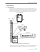
ADCP-75-214 • Issue 2 • September 2006 1 1.1 PRODUCT OVERVIEW General Description The ClearGain 1800 or 2100 MHz Dual Inline Tower Mounted Amplifier (TMA) system are composed of some combination of three functional components: a ClearGain Power Distribution Unit (PDU), a Masthead Unit (MHU) / Tower Mounted Amplifier (TMA), and a Bias-T. Figure 1 shows where these components are located in a typical application on a communications tower.
ADCP-75-214 • Issue 2 • September 2006 1.2 Functional Description The basic purpose of a ClearGain Dual Inline TMA system is to amplify the uplink signal just after the antenna. This is done to compensate for the loss in signal strength that occurs in passage of the signal through the coaxial cable to the Base Transceiver Station (BTS) at the base of the tower. The ClearGain TMA system improves the performance of the BTS by providing 12dB of uplink (reverse path) gain with a low noise figure.
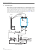
ADCP-75-214 • Issue 2 • September 2006 MHU – located as close to the antenna as possible, performs the amplifier function on the uplink signal. Three subcomponents of the MHU, two RF cavity filters, and a Low Noise Amplifier (LNA), are involved in the amplifier function. Downlink signal is not amplified but passed through an RF cavity filter. PDU – located in the base station, provides DC current to power the LNAs and On/Off Key (OOK) modem signal for use in the Remote Electrical Tilt (RET).
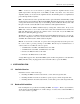
ADCP-75-214 • Issue 2 • September 2006 Note: All hardware is specified in metric units. The threads are sensitive to damage. Figure 3. Typical MHU Clamp Mounting Kit Components 1. When installing on a pole a clamp kit (Figure 3) is required. The kit is designed for tube diameters of 30 to 140 mm. 2. Before going up to the mast, temporarily remove the connector protector plugs, inspect the 7/16 DIN connectors for damage, and return the connector protector plugs to their respective connectors. 3.
ADCP-75-214 • Issue 2 • September 2006 GROUNDING and BONDING CONSIDERATIONS • Grounding is very important in tower top applications. Shipped with each MHU, is a 4mm (#6 AWG), one-meter (39-inch) ground cable with single hole crimp lug connectors on both ends. Installation hardware is provided to attach one end to the MHU. • Keep ground wire as short and direct (no loops or knots) as possible, secure it to a good ground point (metal to metal). • Always follow local grounding practices.
ADCP-75-214 • Issue 2 • September 2006 2.3 PDU Installation 2.3.1 Mechanical Attachment of PDU Warning: Never install the Power Distribution Unit in a wet location or during a lightning storm. When installing or modifying communication lines, disconnect lines at the interface before working with uninsulated lines or terminals to prevent electrical shock. The PDU should be mounted in accordance with local code using appropriate hardware.
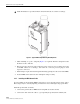
ADCP-75-214 • Issue 2 • September 2006 2.3.1.3 Rack Mount (Optional) A mounting bracket, shown in Figure 5 is available that allows the PDU to be mounted in a rack. If mounting PDU in a rack, refer to the installation drawing provided with the mounting bracket. RACK MOUNTING BRACKET 21300-A Figure 5. PDU Rack Mount Bracket 2.3.2 Installation of PDU Cables There are fife PDU cables: • • • • • Power cable Alarm cable Communication cables MHU (Bias-T) cables Ground cable.
ADCP-75-214 • Issue 2 • September 2006 Figure 6 shows the cable terminations on the front of the PDU. Connect the cables as follows: (Left to Right: Power Cable, Alarm Cable, RS-485, Three MHU (Bias-T) Cables, and Ground Cable) Figure 6. Cable Terminations on Front of PDU 1. Connect the ground cable under the grounding screw on the PDU front panel. Connect the other end of the cable to the site-grounding pole. 2. Connect the alarm cable leads to the base station or site alarm system.
ADCP-75-214 • Issue 2 • September 2006 POWER DISTRIBUTION UNIT PDU ALALRM LOG IC DC INPUT OUTPUT 21307-B NO (NO RMALLY OPEN) COM (CO MMO N) NC (NO RMALLY CLOSED) G ND RS 485A RS 485B Figure 7. PDU Alarm Logic and RS-485 Connections 2.3.3 Setting the DIP Switch on the PDU PDU has one set of dip switches to enable or disable the MHU ports. To disconnect unused MHU output (see Figure 8). For the MHU outputs that are used, the DIP switch must be in the “down” position or “ON”.
ADCP-75-214 • Issue 2 • September 2006 2.4 Bias-T Installation 2.4.1 Mechanical Attachment and Cable Connections Caution: Prior to installing any Bias-T unit, ensure that the BTS transmitter output is turned off and that precautions are taken to ensure that the transmitter cannot be activated during the equipment installation. The Bias-T is installed either inline with the antenna feeder cable or directly to the BTS antenna port. Integrated lightning protection is built into each Bias-T unit.
ADCP-75-214 • Issue 2 • September 2006 3 TROUBLESHOOTING When a fault occurs with the system, the red alarm LED on the PDU and the PDU dry-alarm contact are activated. In such a case, troubleshoot for problems as follows: 1. Check that power is present at the PDU. The PDU will not operate if DC is not present, polarity is incorrect, or the DC presented is out of specifications (–56 to –20 VDC or +20 to +56 VDC). 2. Each MHU output has a status LED. Status LED for each MHU that is in use should be GREEN.
ADCP-75-214 • Issue 2 • September 2006 4 TROUBLESHOOTING 4-PORT CLEARGAIN DUAL INLINE DUAL DUPLEX TOWER MOUNTED AMPLIFIERS Trouble is visually indicated by LED's or no LED illumination on a specific MHU, swap Bias-T cables on PDU ports to see if trouble remains or moves (reference Figure 8). See Figure 10 for possible trouble points. ANTENNA JUMPER FEEDLINE JUMPERS ANTENNA JUMPER MASTHEAD UNIT (MHU) HARD LINE NOTE: COMMON FAILURE POINTS ARE THE ANTENNA AND FEEDLINE JUMPERS/ CONNECTORS.
ADCP-75-214 • Issue 2 • September 2006 4.1 Troubleshooting 1. Observe and record PDU LED status. Disable or disconnect RF from BTS. Remove any surge protectors. Disconnect Bias-T from the antenna feedline / hardline / jumper / protector. FEED LINE PDU 2. Multimeter checks: a. Measure voltage on the Bias-T _______ VDC. Normal is 15 VDC. PDU b. Measure resistance of the feedline _______ Ohms. Normal is High or Very high Ω (KΩ/ΜΩ). FEED LINE 3. Antenna/cable analyzer checks.
ADCP-75-214 • Issue 2 • September 2006 4. Re-connect Bias-T with a T adapter. Verify voltage on the T adapter _______ VDC. Normal is 15 VDC. PDU 5. Re-connect to original configuration and return to service. PDU should illuminate a green LED for each active TMA if there are no faults in the system. 6. Check with operators for improved performance. 4.2 Troubleshooting Hints • If voltage is outside of the normal range, trace it back towards the fault.
ADCP-75-214 • Issue 2 • September 2006 4.3 Troubleshooting Flowchart (For Systems With Three-Port MHUs) If directed by the flowchart, refer to the troubleshooting matrix in Section 4.4 or to the return loss sweep guide in Section 4.5. START • CHECK SUPPLY IS -56 to -20 VDC or +20 to +56 VDC. ANY LIGHTS ON THE PDU? The red lead is connected to the higher potential. NO • CHECK DC CABLE AND CONNECTION.PROBLEM The red Fail led should come on when any MHU select dip switch is pushed to the down position.
ADCP-75-214 • Issue 2 • September 2006 4.4 Troubleshooting Matrix If directed in Section 4.3 to consult a troubleshooting matrix, see Table 1 below. Note: ClearGain PDU DIP switches must be in the down position for each active MHU! Note: ClearGain PDU input voltage must be in the range –56 to –20 VDC or +20 to +56 VDC. Table 1.
ADCP-75-214 • Issue 2 • September 2006 4.5 Return Loss Sweep Guide RETURN LOSS SWEEP GUIDE FOR THE RECEIVE SECTION OF THE MHUs. GOOD 0 BAD -5 -10 RL dB -15 -20 -25 v1 v2 v1 v2 -30 -35 -40 -45 NORMAL IN-SYSTEM SWEEP. TYPICAL. DEGRADATION FROM NORMAL SYSTEM SWEEP. RL IS STILL GOOD IN RX BAND. RECOMMEND CONNECTOR/LINE/ANTENNA CHECKS DURING NEXT SCHEDULED MAINTENANCE PERIOD WHEN TOWER CREW AVAILABLE. RESISTANCE LOOKING INTO THE FEEDLINE SHOULD INDICATE HIGH OR INFINITE OHMS.
ADCP-75-214 • Issue 2 • September 2006 5 5.1 SPECIFICATIONS 1800 Masthead Unit Table 2 provides typical specifications for the 1800 Masthead Unit. Table 2. 1800 Masthead Unit Specifications CATEGORY PARAMETER SPECIFICATION Filters RX (up link) frequency range 1710–1785 MHz TX (down link) frequency range 1805–1880 MHz Tx path Insertion Loss 0.7 dB Power Handling Capability 200W Return Loss 18 dB Gain 12 ± 1 dB Noise Figure < 1.6 dB IIP3 > + 13 dBm Bypass Loss < 2.
ADCP-75-214 • Issue 2 • September 2006 5.2 2100 Masthead Unit Table 3 provides typical specifications for the 2100 Masthead Unit. Table 3. 2100 Masthead Unit Specifications CATEGORY PARAMETER SPECIFICATION Filters RX (up link) frequency range 1920–1980 MHz TX (down link) frequency range 2110–2170 MHz Tx path Insertion Loss 0.5 dB Power Handling Capability 200W Return Loss 18 dB Gain 12 ± 1 dB Noise Figure < 1.7 dB IIP3 > + 13 dBm Bypass Loss < 2.0 dB Dimensions (W x H x D) 166.
ADCP-75-214 • Issue 2 • September 2006 5.3 PDU (Power Distribution Unit) Table 4 provides typical specifications for the PDU. Table 4. Power Distribution Unit (PDU) Specifications CATEGORY PARAMETER SPECIFICATION Electrical Input voltage range 20–56VDC positive/negative ground (Input polarization protected) Output voltage 15V, 4% (Over voltage protection) Output voltage accuracy 4% in 20mA – 400mAMAX 10% in 1.
ADCP-75-214 • Issue 2 • September 2006 5.4 Bias-T Table 5 provides typical specifications for the Bias-T. Table 5. Bias-T Specification CATEGORY PARAMETER SPECIFICATION RF Path Frequency Rangy (MHz) 800–2200 Insertion Loss (max) 0.2 dB Return Loss (min) 19 dB Power Handling (max) 500W RMS Isolation (RF to DC port) > 30 dB Inter modulation (3rd order) 2x20W tones <–108 dBm DC Input Voltage 5–24 V Input Current 0–2 A DC Path Resistance < 1 Ohm Dimension (HxWxD) mm 55.5 x 95.0 x 40.
ADCP-75-214 • Issue 2 • September 2006 6 CUSTOMER INFORMATION AND ASSISTANCE PHONE: U.S.A.