AD-75D II (Gas/Electric/Steam) Installation Manual WARNING: For your safety the information in this manual must be followed to minimize the risk of fire or explosion or to prevent property damage, personal injury or death. AVERTISSEMENT: Assurez-vous de bien suivre les instructions données dans cette notice pour réduire au minimum le risque d’incendie ou d’explosion ou pour éviter tout dommage matériel, toute blessure ou la mort.
Retain This Manual In A Safe Place For Future Reference American Dryer Corporation products embody advanced concepts in engineering, design, and safety. If this product is properly maintained, it will provide many years of safe, efficient, and trouble-free operation. ONLY qualified technicians should service this equipment. OBSERVE ALL SAFETY PRECAUTIONS displayed on the equipment or specified in the installation manual included with the dryer.
IMPORTANT YOU MUST DISCONNECTAND LOCKOUT THE ELECTRIC SUPPLY AND THE GAS SUPPLY OR THE STEAM SUPPLY BEFORE ANY COVERS OR GUARDS ARE REMOVED FROM THE MACHINE TO ALLOW ACCESS FOR CLEANING, ADJUSTING, INSTALLATION, OR TESTING OF ANY EQUIPMENT PER OSHA (Occupational Safety and Health Administration) STANDARDS. “Caution: Label all wires prior to disconnection when servicing controls. Wiring errors can cause improper operation.
WARNING The dryer must never be operated with any of the back guards, outer tops, or service panels removed. PERSONAL INJURY OR FIRE COULD RESULT. WARNING DRYER MUST NEVER BE OPERATED WITHOUT THE LINT FILTER/SCREEN IN PLACE, EVEN IF AN EXTERNAL LINT COLLECTION SYSTEM IS USED. IMPORTANT PLEASE OBSERVE ALL SAFETY PRECAUTIONS displayed on the equipment and/or specified in the installation manual included with the dryer.
Table of Contents SECTION I IMPORTANT INFORMATION ............................................................................. 3 A. Receiving and Handling ........................................................................................................... 3 B. Safety Precautions .................................................................................................................. 4 SECTION II SPECIFICATIONS/COMPONENT IDENTIFICATION ................................... 6 A.
SECTION VI ROUTINE MAINTENANCE ............................................................................... 44 A. Cleaning .............................................................................................................................. 44 B. Adjustments......................................................................................................................... 45 C. Lubrication ......................................................................................................
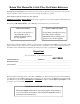
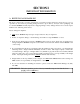
SECTION I IMPORTANT INFORMATION A. RECEIVING AND HANDLING The dryer is shipped in a protective stretch wrap cover with protective cardboard corners and top cover (or optional box) as a means of preventing damage in transit. Upon delivery, the dryer and/or packaging, and wooden skid should be visually inspected for shipping damage. If any damage whatsoever is noticed, inspect further before delivering carrier leaves. Dryers damaged in shipment. 1.
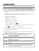
B. SAFETY PRECAUTIONS WARNING: For your safety, the information in this manual must be followed to minimize the risk of fire or explosion or to prevent property damage, personal injury, or loss of life. WARNING: The dryer must never be operated with any of the back guards, outer tops, or service panels removed. PERSONAL INJURY OR FIRE COULD RESULT. 1. DO NOT store or use gasoline or other flammable vapors and liquids in the vicinity of this or any other appliance. 2.
7. A program should be established for the inspection and cleaning of lint in the heating unit area, exhaust ductwork, and inside the dryer. The frequency of inspection and cleaning can best be determined from experience at each location. WARNING: The collection of lint in the burner area and exhaust ductwork can create a potential fire hazard. 8. For personal safety, the dryer must be electrically grounded in accordance with local codes and/or the National Electrical Code ANSI/NFPA NO.
SECTION II SPECIFICATIONS/COMPONENT IDENTIFICATION A. SPECIFICATIONS MAXIMUM CAPACITY (DRY WEIGHT) BASKET (TUMBLER) DIAMETER 75 lbs 37” 34 kg 94 cm BASKET (TUMBLER) DEPTH 36” 91.5 cm BASKET (TUMBLER) MOTOR 1 HP* 0.746 kw DOOR OPENING (DIAMETER) Steam Electric Gas BASKET (TUMBLER) VOLUME DRYERS PER 20’/40’ CONTAINER DRYERS PER 45’/53’ TRUCK 21-1/2” 54.61 cm 22.4 cu. ft. 0.634 cu.m. 10/20 24/26 VOLTAGE AVAILABLE APPROX. WEIGHT (UNCRATED) APPROX.
Specifications ADG-75D (Gas) ADE-75 (Electric) ADS-75 (Steam) NOTE: ADC reserves the right to make changes in specifications at any time without notice or obligation.
B. COMPONENT IDENTIFICATION 1. Dryer Front View Illus. No.
2. Dryer Rear View Illus. No. 1 2 3* 4 5 6 7 8 9 * Description Heating Unit 1/8-inch Compressed Air Supply Inlet (behind electric service relay box for steam units only) Electric Service Relay Box Basket (Tumbler) Bearing Mount Assembly Idler Bearing Mount Assembly Blower Motor Assembly Leveling Leg (rear) Basket (Tumbler) (Drive) Motor Assembly (reversing models only) Dryer Exhaust Electric service connections for gas and steam models are made in this box.
SECTION III INSTALLATION PROCEDURES Installation should be performed by competent technicians in accordance with local and state codes. In the absence of these codes, the installation must conform to applicable American National Standards: ANSI Z223.1LATEST EDITION (National Fuel Gas Code) or ANSI/NFPA NO. 70-LATEST EDITION (National Electrical Code) or in Canada, the installation must conform to applicable Canadian Standards: CAN/CGA-B149.1-M91 (Natural Gas) or CAN/CGA-B149.2-M91 (Liquid Propane [L.P.
B. UNPACKING/SETTING UP Remove protective shipping material (i.e., plastic wrap, and/or optional shipping box) from dryer. IMPORTANT: Dryer must be transported and handled in an upright position at ALL times. The dryer can be moved to its final location while still attached to the skid or with the skid removed. To unskid the dryer, locate and remove the four (4) bolts securing the base of the dryer to the wooden skid.
C. DRYER ENCLOSURE REQUIREMENTS Bulkheads and partitions should be made of noncombustible materials and must be located a minimum of 12-inches (30.48 cm) (18-inches [45.72 cm] or more is recommended for ease of installation, maintenance, and service) above the dryer outer top, except along the front of the dryer which may be partially closed in if desired. The clearance between the bulkhead header and the dryer must be a minimum of 4-inches (10.16 cm) and must not extend more than 4-inches (10.
D. FRESH AIR SUPPLY REQUIREMENTS When the dryer is operating, it draws in room air, heats it, passes this air through the basket (tumbler), and exhausts it out of the building. Therefore, the room air must be continually replenished from the outdoors. If the make-up air is inadequate, drying time and drying efficiency will be adversely affected. Ignition problems and sail switch “fluttering” problems may result, as well as premature motor failure from overheating.
E. EXHAUST REQUIREMENTS 1. General Exhaust Ductwork Information Exhaust ductwork should be designed and installed by a qualified professional. Improperly sized ductwork will create excessive back pressure which results in slow drying, increased use of energy, overheating of the dryer, and shutdown of the burner by the airflow (sail) switches, burner hi-limits, or basket (tumbler) hi-heat thermostats. The dryer must be installed with a proper exhaust duct connection to the outside.
IMPORTANT: Minimum ductwork diameter for horizontal venting is 10-inches (25.4 cm) and for vertical venting the minimum is 12-inches (30.48 cm). NOTE: When the exhaust ductwork passes through a wall, ceiling, or roof made of combustible materials, the opening must be 2-inches (5.08 cm) larger than the duct (all the way around). The duct must be centered within this opening. a.
IMPORTANT: Minimum duct size for a dryer that is vented vertically is 12-inches (30.48 cm) for a round duct or an equivalent of 120 square inches (774 square centimeters). THE DUCT SIZE MUST NOT BE REDUCED ANYWHERE DOWNSTREAM OF THE DRYER. IMPORTANT: For extended ductwork runs, the cross section area of the ductwork can only be increased to an extent.
3. Multiple Dryer (Common) Venting If it is not feasible to provide separate exhaust ducts for each dryer, ducts from individual dryers may be channeled into a “common main duct.” The individual ducts should enter the bottom or side of the main duct at an angle not more than 45º in the direction of airflow and should be spaced at least 38-1/4” (97.2 cm) apart. The main duct should be tapered, with the diameter increasing before each individual duct (10inch [25.4 cm] minimum) is added.
18
F. ELECTRICAL INFORMATION 1. Electrical Requirements It is your responsibility to have ALL electrical connections made by a properly licensed and competent electrician to assure that the electrical installation is adequate and conforms to local and state regulations or codes. In the absence of such codes, ALL electrical connections, materials, and workmanship must conform to the applicable requirements of the National Electrical Code ANSI/NFPA NO.
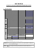
2. Electrical Service Specifications a. Gas and Steam Models Only ADG-75D (Gas) ADS-75D (Steam) IMPORTANT: 208 VAC AND 230/240 VAC ARE NOT THE SAME. When ordering, specify exact voltage. NOTES: A. When fuses are used they must be dual element, time delay, current limiting, class RK1 or RK5 ONLY. Calculate/determine correct fuse value, by applying either local and/or National Electrical Codes to listed appliance amp draw data. B. Circuit breakers are thermal-magnetic (industrial) motor curve type ONLY.
b. Electric Models Only ADE-75D (Electric) IMPORTANT: 208 VAC AND 230/240 VAC ARE NOT THE SAME. When ordering, specify exact voltage. NOTES: A. When fuses are used they must be dual element, time delay, current limiting, class RK1 or RK5 ONLY. Calculate/determine correct fuse value, by applying either local and/or National Electrical Codes to listed appliance amp draw data. B. Circuit breakers are thermal magnetic (industrial) type ONLY.
3. Grounding A ground (earth) connection must be provided and installed in accordance with state and local codes. In the absence of these codes, grounding must conform to applicable requirements of the National Electrical Code ANSI/NFPA NO. 70-LATEST EDITION, or in Canada, the installation must conform to applicable Canada Standards: Canadian Electrical Codes Parts 1 & 2 CSA C22.1-1990 or LATEST EDITION. The ground connection may be to a proven earth ground at the location service panel.
Single-Phase (1Ø) Electrical Connections Leads Black + Positive White + Neutral Green + Ground or L2 If local codes permit, power to a gas or steam dryer can be made by the use of a flexible U.L. listed power cord/pigtail (wire size must conform to rating of dryer), or the dryer can be hard wired directly to the service breaker panel. In ALL cases, a strain relief must be installed where the wiring enters the dryer.
If local codes permit, power to a gas or steam dryer can be made by the use of a flexible U.L. listed power cord/pigtail (wire size must conform to rating of dryer), or the dryer can be hard wired directly to the service breaker panel. In ALL cases, a strain relief must be installed where the wiring enters the dryer. The only electrical input connections to the dryer are the 3-phase (3Ø) power leads (L1, L2, L3, and sometimes neutral) and ground.
3) 3-Phase (3Ø) Wiring Connections/Hookup “Reversing Models Only” The electricalconnections on ALL 3-phase (3Ø) gas and steam dryers are made into the rear service box located at the upper left area of the dryer. Electrical connections for electrically heated dryers are made in the electric oven area located at the upper rear area of the dryer. IMPORTANT: A separate circuit servicing each dryer must be provided. If local codes permit, power to a gas or steam dryer can be made by the use of a flexible U.L.
a) Electrically Heated Models Only The only electrical input connections to the dryer are the 3-phase (3Ø) power leads (L1, L2, L3, and sometimes neutral) and ground. Single-phase (1Ø) power for the control circuit and for any single-phase (1Ø) motors (if present) is done internally to the dryer by the factory at the oven contactor. No single-phase (1Ø) input connection is required on a 3-phase (3Ø) dryer. CAUTION: The dryer must be grounded. A ground lug has been provided for this purpose.
G. GAS INFORMATION It is your responsibility to have ALL plumbing connections made by a qualified professional to assure that the gas plumbing installation is adequate and conforms to local and state regulations or codes. In the absence of such codes, ALL plumbing connections, materials, and workmanship must conform to the applicable requirements of the National Fuel Gas Code ANSI Z223.1-LATEST EDITION, or in Canada, the Canadian Installation Codes CAN/CGA-B149.1-M91 (Natural Gas) or CAN/CGA-B149.
2. Technical Gas Data a. Gas Specifications TYPE OF GAS NATURAL Manifold Pressure* In-Line Pressure LIQUID PROPANE 3.5 inches W.C. 8.7 mb 10.5 inches W.C. 26.1 mb 6.0 - 12.0 inches W.C. 14.92 - 29.9 mb 11.0 inches W.C. 27.4 mb Shaded areas are stated in metric equivalents * Measured at outlet side of gas valve pressure tap when gas valve is on. b. Gas Connections: Inlet connection ------------ 3/4” N.P.T. Inlet supply size ------------ 3/4” N.P.T.
3. Piping/Connections ALL components/materials must conform to National Fuel Gas Code Specifications ANSI Z223.1-LATEST EDITION, or in Canada, CAN/CGA-B149.1-M91 (Natural Gas) or CAN/CGA-B149.2-M91 (Liquid Propane [L.P.] Gas) or LATEST EDITION (for General Installation and Gas Plumbing), as well as local codes and ordinances and must be done by a qualified professional.
Consistent gas pressure is essential at ALL gas connections. It is recommended that a 3/4-inch (19.05 mm) pipe gas loop be installed in the supply line servicing a bank of dryers. An in-line pressure regulator must be installed in the gas supply line (header) if the (natural) gas pressure exceeds 12.0 inches (29.9 mb) of water column (W.C.) pressure. NOTE: A water column test pressure of 3.5 inches (8.7 mb) for natural gas and 10.5 inches (26.1 mb) for liquid propane (L.P.
H. STEAM INFORMATION It is your responsibility to have ALL plumbing connections made by a qualified professional to assure that the steam plumbing installation is adequate and conforms with local and state regulations or codes. IMPORTANT: Failure to comply with the requirements stipulated in this manual can result in component failure, which will VOID THE WARRANTY. NOTE: The ADS-75D is manufactured with a pneumatic (piston) damper system, which requires an external supply of air (80 PSI +/- 10 PSI [5.
a. The pressure of the condensate in the steam supply will cause water hammer and subsequent heat exchanger (steam coil) failure. The steam supply connection into the main supply line must be made with a minimum 10-inch (25.4 cm) riser. This will prevent any condensate from draining towards the dryer. b. The steam supply piping to the dryer must include a 12-inch (30.48 cm) rise along with a drip trap and check valve. This will prevent any condensate from entering the steam coil. c.
4. Steam Damper Air System Connections The ADS-75D is manufactured with a pneumatic (piston) damper system, which requires an external supply of compressed air. The air connection is made to the steam damper solenoid valve, which is located at the rear inner top area of the dryer just in front of the electric service relay box. a. Air Requirements COM P RESSED AIR SUPPLY AIR PRESSURE Normal 80 PSI 5.51 bars Minimum Supply 70 PSI 4.82 bars Maximum Supply 90 PSI 6.
5. Steam Damper System Operation The ADS-75D steam damper shown in Diagram 1 in the illustration below, allows the coil to stay constantly charged eliminating repeated expansion and contraction. When the damper is opened, the air immediately passes through the already hot coil, providing instant heat to start the drying process. When the damper is closed, ambient air is drawn directly into the basket (tumbler), allowing a rapid cool down (Diagram 2).
6. Steam Damper Air Piston (Flow Control) Operation Adjustment Although the steam damper operation was tested and adjusted prior to shipping at 80 PSI (5.51 bars), steam damper operation must be checked before the dryer is put into operation. Refer to page 34 for instructions to check steam damper system operation. If steam damper adjustment is necessary, locate the flow control valve and make the necessary adjustments as noted below.
I. PREPARATION FOR OPERATION/START-UP The following items should be checked before attempting to operate the dryer: 1. Read ALL “CAUTION,” “WARNING,” and “DIRECTION” labels attached to the dryer. 2. Check incoming supply voltage to be sure that it is the same as indicated on the dryer data label affixed to the left side panel area behind the top control (access) door. In the case of 208 VAC or 230/240 VAC, the supply voltage must match the electric service exactly. 3.
J. PREOPERATIONAL TESTS ALL dryers are thoroughly tested and inspected before leaving the factory. However, a preoperational test should be performed before the dryer is publicly used. It is possible that adjustments have changed in transit or due to marginal location (installation) conditions. 1. Turn on electric power to the dryer. a. Open ALL shutoff valves (gas models only). 2. Refer to the Operating Instructions for starting your particular model dryer.
Electrically Heated Dryers Check to insure that electric oven/contactor assembly is activating. 3. Make a complete operational check of ALL safety related circuits: a. Door Switch(es) b. Hi-Limit Thermostats c. Sail Switch (for gas and electric models only) NOTE: To check for proper sail switch operation (for gas and electric models only), open the main door and while holding main door switch plunger in, start dryer. Dryer should start but heat circuit should not be activated (on).
7. Reversing Models Only Basket (tumbler) dryer should never be operated with less than a 30 lb (14 kg) load (dry weight). The size of the load will affect the coast-down and dwell (stop) times. The basket (tumbler) must come to a complete stop before starting in opposite direction. a.
L. SHUT DOWN INSTRUCTIONS If the dryer is to be shut down (taken out of service) for a period of time, the following must be performed: 1. Discontinue power to the dryer either at the external disconnect switch or the circuit breaker. 2. Discontinue the heat supply: a. GAS MODELS...discontinue the gas supply. 1) SHUT OFF external gas supply shutoff valve. 2) SHUT OFF internal gas supply shutoff valve located in the gas valve burner area. b. STEAM MODELS...discontinue the steam supply.
SECTION IV SERVICE/PARTS INFORMATION A. SERVICE 1. Service must be performed by a qualified trained technician, service agency, or gas supplier. If service is required, contact the reseller from whom the ADC equipment was purchased. If the reseller cannot be contacted or is unknown, contact the ADC Service Department for a reseller in your area.
SECTION V WARRANTY INFORMATION A. RETURNING WARRANTY CARDS 1. Before any dryer leaves the ADC factory test area, a warranty card is placed on the back side of the main door glass. These warranty cards are intended to serve the customer where we record the individual installation date and warranty information to better serve you should you file a warranty claim. a. If a warranty card did not come with your dryer, contact the ADC Warranty Department or the ADC Service Department at (508) 678-9000.
2. Each part must be tagged with the following information: a. Model number and serial number of the dryer from which part was removed. b. Nature of failure (be specific). c. Date of dryer installation. d. Date of part failure. e. Specify whether the part(s) being returned is for a replacement, a credit, or a refund. NOTE: If a part is marked for a credit or a refund, the invoice number covering the purchase of the replacement part must be provided. NOTE: Warranty tags (ADC Part No.
SECTION VI ROUTINE MAINTENANCE A. CLEANING A program and/or schedule should be established for periodic inspection, cleaning, and removal of lint from various areas of the dryer, as well as throughout the ductwork system. The frequency of cleaning can best be determined from experience at each location. Maximum operating efficiency is dependent upon proper air circulation. The accumulation of lint can restrict this airflow.
WARNING: When cleaning steam coil fins, be careful not to bend the fins. If fins are bent, straighten by using a fin comb, which is available from local air conditioning supply house. 90 DAYS 1. Remove lint from around basket (tumbler), drive motors, and surrounding areas. 2. Remove lint from gas valve burner area with a dusting brush or vacuum cleaner attachment. 3. Clean any lint accumulation in and around both the blower and drive motor casing openings.
C. LUBRICATION The motor bearings, idler bearings...and under normal/most conditions the basket (tumbler) bearings are permanently lubricated. It is physically possible to relubricate the basket (tumbler) bearings if you choose to do so even though this practice is not necessary. Use Shell Alvania #2 grease or its equivalent. The basket (tumbler) bearings used in the dryer DO NOT have a grease fitting.
SECTION VII PROCEDURE FOR FUNCTIONAL CHECK OF REPLACEMENT COMPONENTS 1. Microprocessor Controller (Computer) Board a. Upon completing installation of the replacement microprocessor controller (computer) board, reestablish power to the dryer. b. Start the drying cycle by pressing any of the preset cycles in letters A-F. c. Verify that the motor(s) and the heat indicator dots, in the microprocessor controller (computer) light emitting diode (L.E.D.) display are on. (Refer to the illustration below.
d. Verify that the motor(s), heat, and door indicator lights, on the back side of the microprocessor controller (computer) board are lit. (Refer to the illustration below.) e. Open main door. The dryer must stop and ALL output indicator lights on the back side of the microprocessor controller (computer) board must go out. (Refer to the illustration above.) f. Try to restart the dryer with the main door open. g. The microprocessor controller (computer) board’s light emitting diode (L.E.D.
2. For Models With Johnson Controls Direct Spark Ignition (DSI) Module (G760) Theory Of Operation: Start the drying cycle. When the gas burner ignites within the chosen trial for ignition time (6-seconds), the flame sensor detects gas burner flame and signals the DSI module to keep the gas valve open...as long as there is a call for heat. The DSI module will “LOCKOUT” if the gas burner flame is not sensed at the end of the trial for ignition period.
SECTION VIII REVERSING TIMER SPIN/DWELL ADJUSTMENTS Dual timer models with “reversing option” have an electric reversing timer in the electric service box, which is located in the upper rear area of the dryer. Both the dwell (stop) time and basket (tumbler) spin time are adjustable by mode selection switches located on the electronic timer (as noted in the illustration below).
SECTION IX DATA LABEL INFORMATION A. DATA LABEL Contact American Dryer Corporation When contacting American Dryer Corporation certain information is required to insure proper service/parts information from ADC. This information is on the data label located on the left side panel area behind the top control (access) door. When contacting ADC please have the model number and serial number available.
THE DATA LABEL 1. MODEL NUMBER The model number is an ADC number, which describes the size of the dryer and the type of heat (gas, electric, or steam). 2. SERIAL NUMBER The serial number allows ADC to gather information on your particular dryer. 3. MANUFACTURING CODE NUMBER The manufacturing code number is a number issued by ADC, which describes ALL possible options on your particular model. 4.
SECTION X TROUBLESHOOTING WARNING: YOU MUST DISCONNECT AND LOCKOUT THE ELECTRIC SUPPLY AND THE GAS SUPPLY OR THE STEAM SUPPLY BEFORE ANY COVERS OR GUARDS ARE REMOVED FROM THE MACHINE TO ALLOW ACCESS FOR CLEANING, ADJUSTING, INSTALLATION, OR TESTING OF ANY EQUIPMENT PER OSHA (Occupational Safety and Health Administration) STANDARDS. The information provided will help isolate the most probable component(s) associated with the difficulty described.
2. Microprocessor controller (computer) motor indicator dot and relay output light emitting diode (L.E.D.) indicator dots are on, but motor output L.E.D. indicator is off... a. Failed microprocessor controller (computer). C. Drive motor (for reversing models only) operates in one (1) direction only...stops and restarts in the same direction... 1. Failed reversing contactor (relay). 2. Failed arc suppressor (A.S.) board. 3. Failed microprocessor controller (computer), check output indicator. D.
b. Low voltage to motor. c. Failed motor. d. Failed blower (impellor/fan) is out of balance. G. Both drive motor and blower (impellor/fan) motor (for reversing models only) are not operating (does not start), microprocessor controller (computer) motor indicator dots and relay output light emitting diode (L.E.D.) indicators are on... 1. Failed arc suppressor (A.S.) board. 2. Failed contactors (both blower [impellor/fan] motor and drive motor). 3.
a. Main door is not closed ALL the way. b. Main door switch is out of proper adjustment. c. Failed lint main door switch. d. Broken wire/connection in main door wiring circuit. 2. Failed 24 VAC step down transformer. L. Microprocessor controller (computer) light emitting diode (L.E.D.) display reads “door” and the microprocessor controller (computer) “DOOR” L.E.D. indicator is on... 1. Failed microprocessor controller (computer). M.
R. Microprocessor controller (computer) light emitting diode (L.E.D.) display reads “SEFL”... 1. Rotational sensor circuit failure, fault somewhere in the basket (tumbler) rotation or circuit... a. Basket (tumbler) is not rotating... 1) Broken or loose V-belts. 2) Failure in drive motor circuit. (Refer to Section B, Section C, and Section D on page 53 and page 54.) b. Failed rotational sensor. c. Broken wire or connection between rotation sensor and microprocessor controller (computer). S.
b. Sail switch damper is not closing or is fluttering... 1) Lint screen is dirty. 2) Restriction in the exhaust ductwork. 3) No exhaust airflow... a) Failed impellor (fan/blower). b) Fault in blower (impellor/fan) motor circuit (for reversing models only). 2. Tripped manual reset burner hi-limit. 3. Tripped manual reset basket (tumbler) hi-limit. STEAM MODELS... 1. Tripped manual reset basket (tumbler) hi-limit. U. Heating unit is not operating (no heat), voltage is evident at the heating unit (i.e.
b) Restriction in exhaust ductwork. c. Ignitor does not spark and module locks out (“RED” indicator stays on). 1) Fault in high voltage (HV) wire, break or loose connection. 2) Failed ignitor probe assembly. 3) Failed Direct Spark Ignition (DSI) module. ELECTRIC MODELS... 1. Failed oven contactor/coil. 2. Failed electric heating element(s). STEAM MODELS... 1. Air Operated System... a. No (external) compressed air (80 PSI [5.51 bars] is required) to steam damper solenoid. b.
4. Impellor (fan/blower) is rotating in the wrong direction (for 3-phase [3ø] models only). 5. Lint screen is dirty or is not being cleaned often enough. 6. Inadequate airflow... a. Impellor (fan/blower) failure. GAS MODELS... 1. Low and/or inconsistent gas pressure. Natural gas pressure ........................... 3.5 inches (8.7 mb) of water column (W.C.). Liquid propane (L.P.) gas pressure ...... 10.5 inches (26.1 mb) of water column. 2.
STEAM MODELS 1. Low steam supply... a. Steam trap is too small. b. Supply line is too small. 2. Low steam pressure. 3. Insufficient make-up air. 4. Lint screen is dirty or is not being cleaned often enough. 5. Restriction in the exhaust ductwork. 6. Dirty steam coil... a. Fins are clogged with lint. 7. Steam damper system is not functioning properly... a. Steam damper is sticking closed. b. Leak in the pneumatic (air) system. 8. Extractors (washers) are not functioning properly. 9.
a. Not enough make-up air. b. Restriction in the exhaust ductwork. c. Gas pressure is too high. d. Impellor (fan/blower) is rotating in the wrong direction (for 3-phase [3ø] models only). e. Burner orifice size (drill material size [D.M.S.]) too large for application (i.e., high elevation). AA. Condensation on main door glass... 1. Too long, undersized, or improperly installed ductwork. 2. Back draft damper is sticking in the partially closed position. BB. Scraping noise at basket (tumbler) area... 1.
9. Failed motor bearing. DUAL TIMER MODELS A. Dryer will not start, both drive motor and blower (impellor/fan) motor are not operating (DO NOT start) and indicator light is off... 1. Service panel fuse blown or tripped breaker. 2. Dryer control circuit L1 or L2 1/2-amp (slo blo) fuse is blown. 3. Open in main door switch... a. Main door is not closed ALL the way. b. Main door switch is out of proper adjustment. c. Failed main door switch. d. Broken connection/wire somewhere in the main door switch circuit.
b. Low voltage to motor. c. Failed motor. d. Basket (tumbler) is binding, check for an obstruction. e. Failed idler bearings or basket (tumbler) bearings. E. Fan/blower motor is not operating (does not start)... 1. Failed blower (impellor/fan) motor contactor (relay). 2. Failed blower (impellor/fan) motor. F. 1. Fan/blower motor operates okay for a few minutes, then stops and will not restart... Motor is overheating and tripping out on internal overload protector... a.
b) Fault in blower (impellor/fan) motor circuit (for reversing models only). 2. Tripped manual reset burner hi-limit. 3. Tripped manual reset basket (tumbler) hi-limit. ELECTRIC MODELS... 1. Fault in sail switch circuit... a. Sail switch is out of adjustment or has failed. b. Sail switch damper is not closing or is fluttering... 1) Lint screen is dirty. 2) Restriction in the exhaust ductwork. 3) No exhaust airflow... a) Failed impellor (fan/blower).
1) Ignitor probe assembly is out of adjustment or has failed. 2) Severe air turbulence. 3) Failed Direct Spark Ignition (DSI) module. 4) Failed gas valve. b. Ignitor sparks, burner lights but goes off right away... 1) DSI ignitor flame probe is out of adjustment, or has failed. 2) Sail switch is fluttering... a) Lint screen is dirty. b) Restriction in exhaust ductwork. c. Ignitor does not spark and module locks out (“RED” light emitting diode [L.E.D.] indicator stays on)...
J. Dryer operates but is taking too long to dry... 1. Exhaust ductwork run is too long or is undersized, back pressure must be no less than 0 and cannot exceed 0.3 inches (0.74 mb) water column (W.C.). 2. Restriction in exhaust ductwork... a. Dryer back draft damper is sticking partially closed. b. Restriction/obstruction in ductwork... 1) Check ductwork from the dryer ALL the way to the outdoors. 3. Insufficient make-up air. 4.
4. Impellor (fan/blower) is rotating in the wrong direction only (for 3-phase [3ø] models only). 5. Failed electric element(s). 6. Sail switch is fluttering... a. Restriction in the exhaust ductwork. b. Sail switch is not adjusted properly. STEAM MODELS 1. Low steam pressure. 2. Insufficient make-up air. 3. Lint screen is dirty or is not being cleaned often enough. 4. Restriction in the exhaust ductwork. 5. Dirty steam coil... a. Fins are clogged with lint. 6.
d. Impellor (fan/blower) is rotating in the wrong direction (for 3-phase [3ø] models only). e. Burner orifice size (drill material size [D.M.S]) too large for application (i.e., high elevation). L. Condensation on main door glass... 1. Too long, undersized, or improperly installed ductwork. 2. Back draft damper is sticking in the partially closed position. M. Scraping noise at basket (tumbler) area... 1. Check for obstruction caught in basket (tumbler)/wrapper area. 2.
SECTION XI BURNER AND BASKET (TUMBLER)/LINT CHAMBER MANUAL RESET HI-LIMIT INSTRUCTIONS IMPORTANT MANUAL RESET HI-LIMIT INSTRUCTIONS FOR DUAL TIMER OR PHASE 5 WITHOUT HEAT FAULT (GAS MODELS ONLY) This dryer was manufactured with a burner manual reset hi-limit and basket (tumbler)/lint chamber hi-limit thermostat.
IMPORTANT MANUAL RESET HI-LIMIT INSTRUCTIONS FOR DUAL TIMER OR PHASE 5 WITHOUT HEAT FAULT (ELECTRIC OR STEAM MODELS) This dryer was manufactured with a manual reset basket (tumbler)/lint chamber hi-limit thermostat. If the manual reset thermostat is open prior to the start of the drying cycle, or during the cycle, the dryer will not recognize the open state of the hi-limit thermostat and will start or continue through the drying cycle with no heat. Manual reset hi-limit must be reset manually.
ADC 113121 1 - 12/30/99-25 4 - 01/18/00-250 7 - 10/19/00-500 2 - 12/30/99-100 5 - 03/03/00-250 8 * 09/25/01-500 3 - 01/17/00-25 6 - 05/26/00-500